Page 4–114
DURApulse GS4 AC Drive User Manual – 1st Ed, Rev A - 10/20/2017
Chapter 4: AC Drive Parameters
analog inPut ParaMeter exaMPle 2:
standard oPeration with increased MaxiMuM outPut Frequency
This example illustrates how to run the motor faster than its base speed. For this purpose, the
only required parameter change is P0.04, Drive Maximum Output Frequency. (Motors produce
reduced output torque when running above their base speed.)
WARNING: The dRIve MAxIMuM OuTpuT FRequeNcy pARAMeTeR (p0.04) shOuld NeveR exceed The MAxIMuM
speed RATING FOR The MOTOR yOu ARe usING. IF ThIs INFORMATION Is NOT ReAdIly AvAIlAble, cONsulT yOuR
MOTOR MANuFAcTuReR.
The analog input adjustment parameters can remain defaulted, as determined by the analog input
calculations shown below. The increased Drive Maximum Output Frequency can be obtained
regardless of whether the Source of Frequency Command (P4.00 of P4.01) is an analog input or
one of the other sources, such as the keypad, RS-485 communication interface, jog, or multi-speed
settings.
•
Minimum Frequency Reference = 0Hz
•
Maximum Frequency Reference = 70Hz
•
Motor Maximum Output Speed = 2042 rpm
For AI1, AI2, and AI3: P4.24 (AI V/Hz Calculated Selection) MUST BE SET TO ZERO (All Inputs
Use Bias and Gain) TO ENABLE BIAS AND GAIN CALCULATIONS.
Calculations (see page 4–112 for formulas)
A) Drive Maximum Output Frequency = P0.04 = (2042 rpm / 1750 rpm) x 60Hz = 70Hz
B) Analog Offset % = [0Hz / (70Hz)] x 100 = 0%
Analog Input (AIx) AI1 AI2 AI3
AIx Bias Parameter
P4�10 P4�15 P4�19
C) Analog Gain % = [(70Hz – 0Hz) / 70Hz] x 100 = 100% = AIx Input Gain
Analog Input AI1 AI2 AI3
Polarity
Positive (+) Positive (+) Positive (+) Negative (-)
AIx Gain Parameter
P4�12 P4�17 P4�21 P4�22
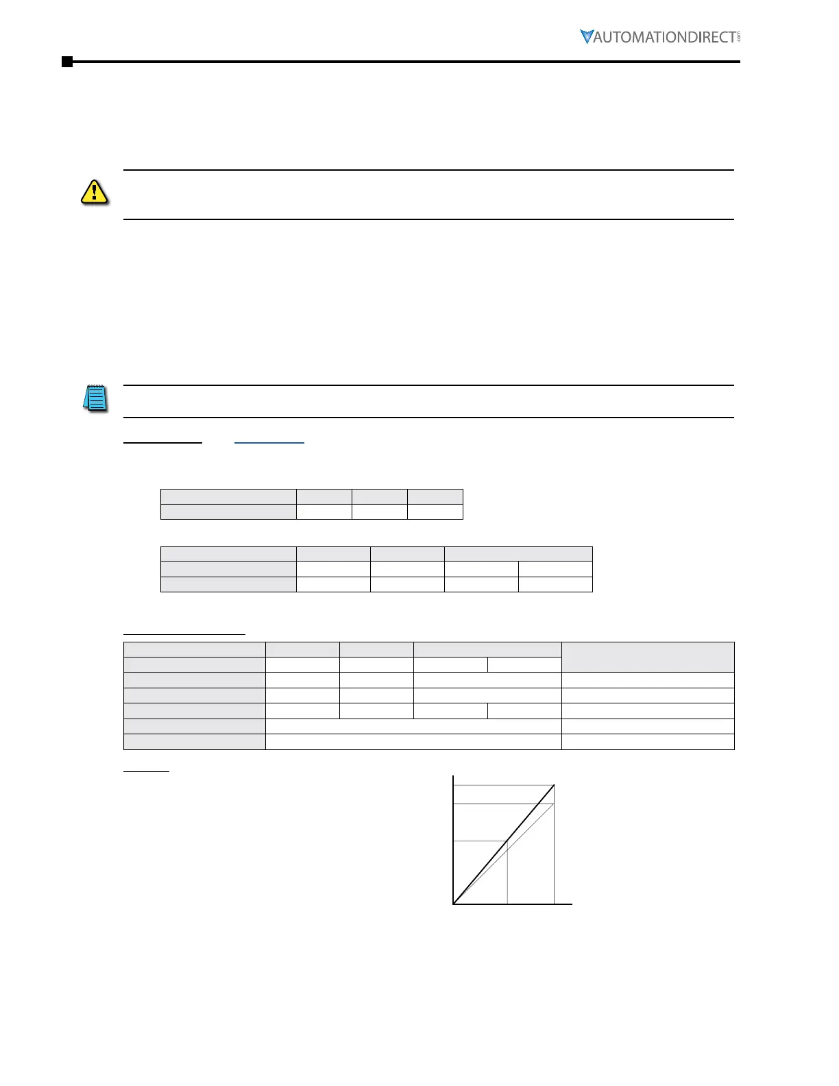
D) Mid-point Frequency = [(70Hz – 0Hz) / 2] + 0Hz = 35Hz
Parameter Settings
Analog Input AI1 or AI2 or AI3
Parameter Settings
Polarity
Positive (+) Positive (+) Positive (+) Negative (-)
AIx Bias Parameter
P4�10 P4�15 P4�19 0�0%
AIx Polarity Parameter
P4�11 P4�16 P4�20 0: No Offset
AIx Gain Parameter
P4�12 P4�17 P4�21 P4�22 100�0%
Reverse Run Parameter
P4�09 0: Digital FWD/REV
Drive Max Output Freq
P0�04 70Hz
Results
Mid-Point Frequency
Motor Base Frequency
35Hz
0Hz
60Hz
0V 5V 10V
-10V0V 10V
0mA10mA 20mA

 Loading...
