Chapter 4: AC Drive Parameters
Page 4–115
DURApulse GS4 AC Drive User Manual – 1st Ed, Rev A - 10/20/2017
analog inPut ParaMeter exaMPle 3: Positive oFFset
In this example, the Analog Input will have a positive offset while still using the full scale of the
potentiometer or other analog signal device. When the analog signal is at its lowest value (-10V,
0V, 0mA, or 4mA), the set-point frequency will be at 10Hz. When analog signal is at its maximum
value (10V or 20mA), the set-point frequency will be 60Hz.
•
Minimum Frequency Reference = 10Hz
•
Maximum Frequency Reference = 60Hz
For AI1, AI2, and AI3: P4.24 (AI V/Hz Calculated Selection) MUST BE SET TO ZERO (All Inputs
Use Bias and Gain) TO ENABLE BIAS AND GAIN CALCULATIONS.
Calculations (see page 4–112 for formulas)
A) Drive Maximum Output Frequency = P0.04 = (1750 rpm / 1750 rpm) x 60Hz = 60Hz
B) Analog Offset % = ( 10Hz / 60Hz ) x 100 = 16.7%
Analog Input (AIx) AI1 AI2 AI3
AIx Bias Parameter
P4�10 P4�15 P4�19
C) Analog Gain % = [(60Hz – 10Hz) / 60Hz] x 100 = 83.3% = AIx Input Gain
Analog Input AI1 AI2 AI3
Polarity
Positive (+) Positive (+) Positive (+) Negative (-)
AIx Gain Parameter
P4�12 P4�17 P4�21 P4�22
D) Mid-point Frequency = [(60Hz – 10Hz) / 2] + 10Hz = 35Hz
Parameter Settings
Analog Input AI1 or AI2 or AI3
Parameter Settings
Polarity
Positive (+) Positive (+) Positive (+) Negative (-)
AIx Bias Parameter
P4�10 P4�15 P4�19 16�7%
AIx Polarity Parameter
P4�11 P4�16 P4�20 1: Positive Offset
AIx Gain Parameter
P4�12 P4�17 P4�21 P4�22 83�3%
Reverse Run Parameter
P4�09 0: Digital FWD/REV
Drive Max Output Freq
P0�04 60Hz
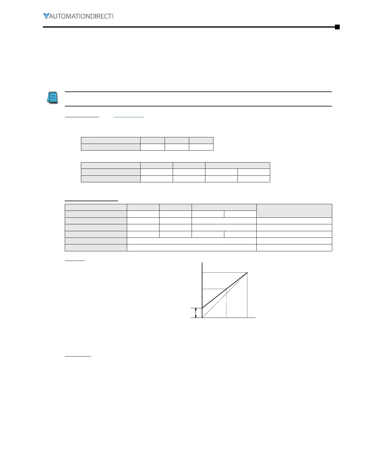
Results
Maximum Output
Frequency
Positive Offset
60Hz
0Hz
10Hz
35Hz
0V 5V 10V
-10V0V 10V
0mA10mA 20mA
Examples
•
Output Freq = [ (Analog_In%) x (Gain%) + (Bias%) ] x Max_Out (Hz)
•
For AI1 set to 0~10V, and an analog input of 1 Volt:
Output Freq = [ (1/10) x (0�833) + (0�167) ] x 60Hz = 15Hz
•
For analog input of 7 Volts:
Output Freq = [ (7/10) x (0�833) + (0�167) ] x 60Hz = 45Hz

 Loading...
