Page 4–116
DURApulse GS4 AC Drive User Manual – 1st Ed, Rev A - 10/20/2017
Chapter 4: AC Drive Parameters
analog inPut ParaMeter exaMPle 4: Forward and reverse oPeration
In this example, the potentiometer (or other analog signal device) is programmed to run a motor
full-speed in both forward and reverse directions. The frequency reference will be 0Hz when the
potentiometer is positioned at mid-point of its scale. Parameter P4.09 must be set to enable
reverse motion.
When calculating the values for the Analog Input using reverse motion, polarity matters in the
Bias/Offset Parameter (P4.10, P4.15, or P4.19) AND in the Polarity Parameter (P4.11, P4.16, or
P4.20). If both parameters are negative, the resulting offset will be positive (double negatives).
If a negative offset is required, either the Bias/Offset value OR the Polarity Parameter needs
to be negative (not both). If your PLC does not handle negative values easily, use the Polarity
Parameter to create a negative bias/offset.
•
Minimum Frequency Reference = -60Hz (reverse)
•
Maximum Frequency Reference = 60Hz
For AI1, AI2, and AI3: P4.24 (AI V/Hz Calculated Selection) MUST BE SET TO ZERO (All Inputs
Use Bias and Gain) TO ENABLE BIAS AND GAIN CALCULATIONS.
Calculations (see page 4–112 for formulas)
A) Drive Maximum Output Frequency = P0.04 = (1750 rpm / 1750 rpm) x 60Hz = 60Hz
B) Analog Offset % = [ (-60Hz) / (60Hz) ] x 100 = -100%
Analog Input (AIx) AI1 AI2 AI3
AIx Bias Parameter
P4�10 P4�15 P4�19
The negative (-) value for the Analog Offset shows that you can use either a negative value in the
Offset/Bias Parameter (P4.10, P4.15, or P4.19) or a negative setting in the Polarity Parameter
(P4.12, P4.17, or P4.21). Do not put a negative into both.
C) Analog Gain % = [ (60Hz – (-60Hz)) / 60Hz ] x 100 = 200% = AIx Input Gain
Analog Input AI1 AI2 AI3
Polarity
Positive (+) Positive (+) Positive (+) Negative (-)
AIx Gain Parameter
P4�12 P4�17 P4�21 P4�22
D) Mid-point Frequency = [ (60Hz – (-60Hz)) / 2 ] + (-60Hz) = 0Hz
Parameter Settings
Analog Input AI1 or AI2 or AI3
Parameter Settings
Polarity
Positive (+) Positive (+) Positive (+) Negative (-)
AIx Bias Parameter
P4�10 P4�15 P4�19 -100�0% *
AIx Polarity Parameter
P4�11 P4�16 P4�20 1: Positive Offset *
AIx Gain Parameter
P4�12 P4�17 P4�21 P4�22 200�0%
Reverse Run Parameter
P4�09 1: AI Bias FWD/REV
Drive Max Output Freq
P0�04 60Hz
* This example uses Bias = -100% and Positive Bias Polarity.
The example will work exactly the same with Bias = +100% and a Negative Bias Polarity.
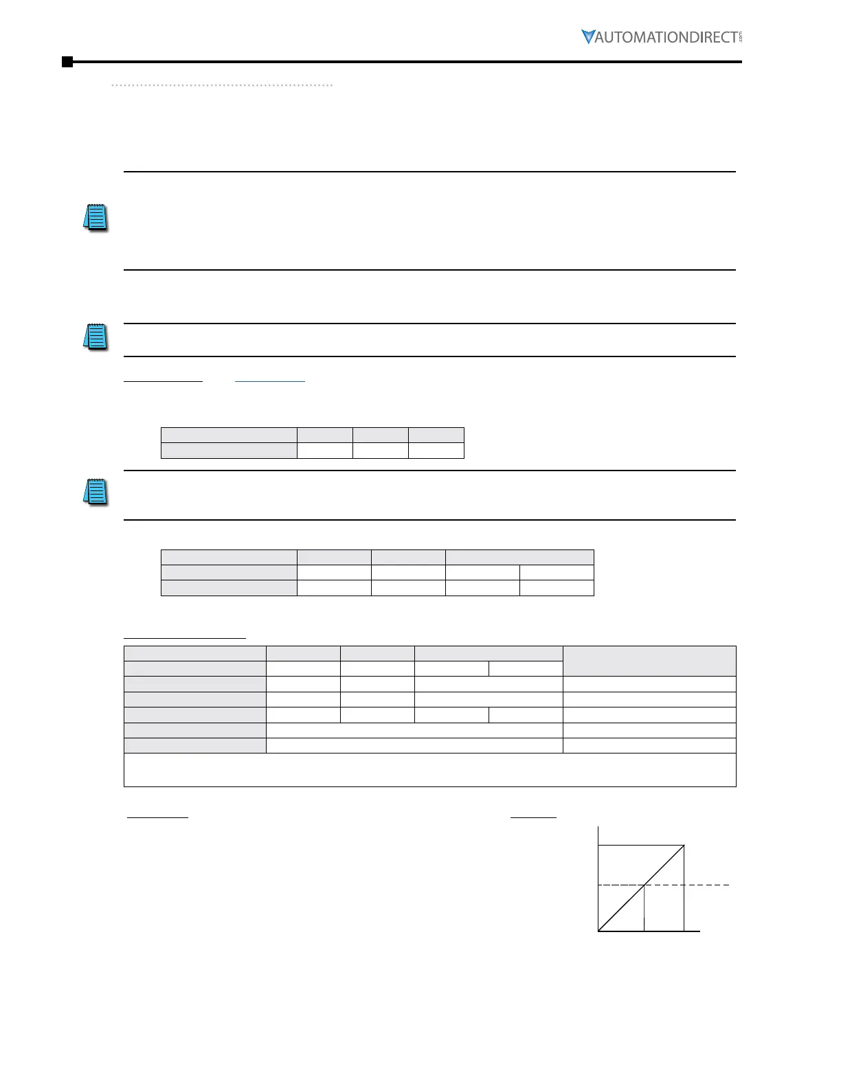
Examples Results
•
Output Freq = [ (Analog_In%) x (Gain%) + (Bias%) ] x
Max_Out (Hz)
•
For AI1 set to 0~10V, and an analog input of 5 Volts:
Output Freq = [ (5/10) x (2�00) + (-1�00) ] x 60Hz = 0Hz
•
For analog input of 10 Volts:
Output Freq = [ (10/10) x (2�00) + (-1�00) ] x 60Hz = 60Hz
Output
60Hz
-60Hz
0Hz
Forward
Reverse
0V 5V 10V
-10V 0V 10V
0mA 10mA 20mA

 Loading...
