Chapter 4: AC Drive Parameters
Page 4–117
DURApulse GS4 AC Drive User Manual – 1st Ed, Rev A - 10/20/2017
analog inPut ParaMeter exaMPle 5: Forward run/reverse Jog
This example shows an application in which the drive runs full-speed forward and jogs in reverse.
The full scale of the potentiometer (or other analog signal device) will be used.
When calculating the values for the Analog Input using reverse motion, the reverse frequency
reference should be shown using a negative (-) number. Pay special attention to signs (+/-) for
values representing reverse motion.
•
Minimum Frequency Reference = -15Hz (reverse)
•
Maximum Frequency Reference = 60Hz
For AI1, AI2, and AI3: P4.24 (AI V/Hz Calculated Selection) MUST BE SET TO ZERO (All Inputs
Use Bias and Gain) TO ENABLE BIAS AND GAIN CALCULATIONS.
Calculations (see page 4–112 for formulas)
A) Drive Maximum Output Frequency = P0.04 = (1750 rpm / 1750 rpm) x 60Hz = 60Hz
B) Analog Offset % = [ (-15Hz) / (60Hz) ] x 100 = -25%
Analog Input (AIx) AI1 AI2 AI3
AIx Bias Parameter
P4�10 P4�15 P4�19
The negative (-) value for the Analog Offset % shows that a negative offset is needed for P4.11,
P4.16, or P4.20, or a negative value in P4.10, P4.15, or P4.19. Do not use negatives in both
parameters.
C) Analog Gain % = [(60Hz – (-15Hz)) / 60Hz] x 100 = 125% = AIx Input Gain
Analog Input AI1 AI2 AI3
Polarity
Positive (+) Positive (+) Positive (+) Negative (-)
AIx Gain Parameter
P4�12 P4�17 P4�21 P4�22
D) Mid-point Frequency = [(60Hz – (-15Hz)) / 2] + (-15Hz) = 22.5Hz
Parameter Settings
Analog Input AI1 or AI2 or AI3
Parameter Settings
Polarity
Positive (+) Positive (+) Positive (+) Negative (-)
AIx Bias Parameter
P4�10 P4�15 P4�19 -25�0% *
AIx Polarity Parameter
P4�11 P4�16 P4�20 1: Positive Offset *
AIx Gain Parameter
P4�12 P4�17 P4�21 P4�22 125�0%
Reverse Run Parameter
P4�09 1: AI Bias FWD/REV
* This example uses Bias = -20% and Polarity = 1: Positive Offset.
The example will work exactly the same with Bias = +20% and Polarity = 2: Negative Offset.
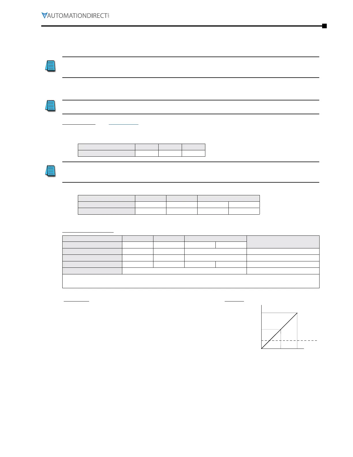
Examples Results
•
Output Freq = [ (Analog_In%) x (Gain%) + (Bias%) ] x
Max_Out (Hz)
•
For AI1 set to 0~10V, and an analog input of 1 Volt:
Output Freq = [ (1/10) x (1�25) + (-0�25) ] x 60Hz = -7�5Hz
•
For analog input of 7 Volts:
Output Freq = [ (7/10) x (1�25) + (-0�25) ] x 60Hz = 37�5Hz
Output
60Hz
-15Hz
22.5Hz
0Hz
Forward
Reverse
0V 5V 10V
-10V 0V 10V
0mA 10mA 20mA

 Loading...
