Page 4–118
DURApulse GS4 AC Drive User Manual – 1st Ed, Rev A - 10/20/2017
Chapter 4: AC Drive Parameters
analog inPut ParaMeter exaMPle 6: reduced analog gain
This example shows how to limit the Maximum Frequency Reference by reducing the Analog Input
Gain. When the Analog Input is at its maximum value (10V or 20mA), the set-point frequency will
be 50Hz. However, this reduced maximum frequency applies only to an Analog Input Source of
Frequncy Command. The Maximum Output Frequency can still can still go to 60Hz if controlled
from the Keypad, RS-485 interface, Jog Command, or Multi-Speed settings.
•
Minimum Frequency Reference = 0Hz
•
Maximum Frequency Reference = 50Hz
For AI1, AI2, and AI3: P4.24 (AI V/Hz Calculated Selection) MUST BE SET TO ZERO (All Inputs
Use Bias and Gain) TO ENABLE BIAS AND GAIN CALCULATIONS.
Calculations (see page 4–112 for formulas)
A) Drive Maximum Output Frequency = P0.04 = (1750 rpm / 1750 rpm) x 60Hz = 60Hz
B) Analog Offset % = [ (0Hz) / (60Hz)] x 100 = 0%
Analog Input (AIx) AI1 AI2 AI3
AIx Bias Parameter
P4�10 P4�15 P4�19
C) Analog Gain % = [(50Hz – 0Hz) / 60Hz] x 100 = 83.3% = AIx Input Gain
Analog Input AI1 AI2 AI3
Polarity
Positive (+) Positive (+) Positive (+) Negative (-)
AIx Gain Parameter
P4�12 P4�17 P4�21 P4�22
D) Mid-point Frequency = [(50Hz – 0Hz) / 2] + 0Hz = 25Hz
Parameter Settings
Analog Input AI1 or AI2 or AI3
Parameter Settings
Polarity
Positive (+) Positive (+) Positive (+) Negative (-)
AIx Bias Parameter
P4�10 P4�15 P4�19 0�0%
AIx Polarity Parameter
P4�11 P4�16 P4�20 0: No Offset
AIx Gain Parameter
P4�12 P4�17 P4�21 P4�22 83�3%
Reverse Run Parameter
P4�09 0: Digital FWD/REV
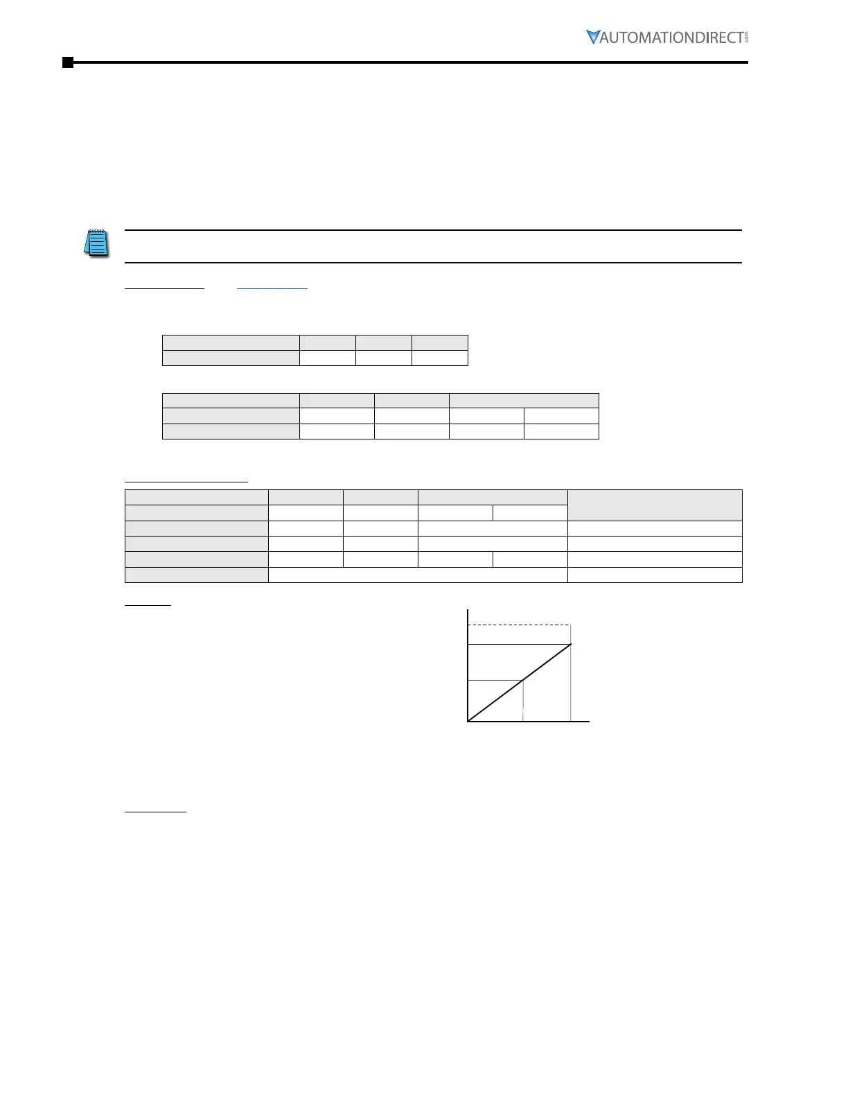
Results
60Hz
25Hz
0Hz
50Hz
Max. Output Frequency
Max. Frequency Reference
0V 5V 10V
-10V0V 10V
0mA10mA 20mA
Examples
•
Output Freq = [ (Analog_In%) x (Gain%) + (Bias%) ] x Max_Out (Hz)
•
For AI1 set to 0~10V, and an analog input of 5 Volts:
Output Freq = [ (5/10) x (0�833) + (0) ] x 60Hz = 25Hz
•
For analog input of 10 Volts:
Output Freq = [ (10/10) x (0�833) + (0) ] x 60Hz = 50Hz

 Loading...
