Page 4–120
DURApulse GS4 AC Drive User Manual – 1st Ed, Rev A - 10/20/2017
Chapter 4: AC Drive Parameters
analog inPut ParaMeter exaMPle 8: triM Mode
This example illustrates using the drive in Trim Mode with a Trim Reference Frequency.
•
Minimum Frequency Reference = 0Hz
•
Maximum Frequency Reference = 45Hz
•
Actual Drive Output Frequency (when P4�08 = 4) = Frequency Command - Trim Reference
Frequency
•
Trim Frequency Reference P4�07 = 15Hz
(use comms or keypad to adjust this value based on the application needs)
For AI1, AI2, and AI3: P4.24 (AI V/Hz Calculated Selection) MUST BE SET TO ZERO (All Inputs
Use Bias and Gain) TO ENABLE BIAS AND GAIN CALCULATIONS.
Calculations (see page 4–112 for formulas)
A) Drive Maximum Output Frequency = P0.04 = (1750 rpm / 1750 rpm) x 60Hz = 60Hz
B) Analog Offset % = [0Hz / (0Hz)] x 100 = 0%
Analog Input (AIx) AI1 AI2 AI3
AIx Bias Parameter
P4�10 P4�15 P4�19
C) Analog Gain % = [(60Hz - 0Hz) / 60Hz] x 100 = 100% = AIx Input Gain
Analog Input AI1 AI2 AI3
Polarity
Positive (+) Positive (+) Positive (+) Negative (-)
AIx Gain Parameter
P4�12 P4�17 P4�21 P4�22
D) Mid-point Frequency = [(45Hz – 0Hz) / 2] + 0Hz = 22.5Hz
E) Actual Output Frequency
P4.08=04
= Freq Command – Trim Ref Freq
Parameter Settings
Analog Input AI1 or AI2 or AI3
Parameter Settings
Polarity
Positive (+) Positive (+) Positive (+) Negative (-)
AIx Bias Parameter
P4�10 P4�15 P4�19 0�0%
AIx Polarity Parameter
P4�11 P4�16 P4�20 0: No Offset
AIx Gain Parameter
P4�12 P4�17 P4�21 P4�22 100�0%
Reverse Run Parameter
P4�09 1: AI Bias FWD/REV
Trim Selection
P4�08 4: Speed Source - Trim Ref Freq
Trim Reference Freq
P4�07 15�00Hz
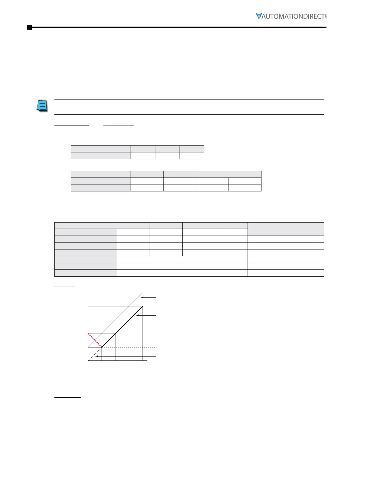
Results
0Hz
30Hz
60Hz
-15Hz
15Hz
45Hz
Frequency Command
Output Frequency
The drive will not reverse direction unless the Frequency Command
is from an analog input, and reverse motion is enabled in P4.09.
If negative motion is disabled (P4.09=0), the analog signal will be
treated as an absolute value. Instead of 0Hz output below 2.5V
analog input, the Hz output will be treated as an absolute value and
will follow the red line below 2.5V. To establish 0Hz below a specific
analog threshold, please see Analog Input Parameter Example 9.
0V 2.5V 5V 10V
-10V -5V0V10V
0mA 5mA 10mA 20mA
4mA 8mA 12mA 20mA
FORWARD
Examples
•
Output Freq = [ [ (Analog_In%) x (Gain%) + (Bias%) ] x Max_Out (Hz) ] - Trim Freq (when P4�08=4)
•
For AI1 set to 0~10V, and an analog input of 5 Volts:
Output Freq = [ [ (5/10) x (1�00) + (0) ] x 60Hz ] - 15 = 15Hz
•
For analog input of 10 Volts:
Output Freq = [ [ (10/10) x (1�00) + (0) ] x 60Hz ] - 15 = 45Hz

 Loading...
