Chapter 4: AC Drive Parameters
Page 4–165
DURApulse GS4 AC Drive User Manual – 1st Ed, Rev A - 10/20/2017
Type Hex Addr Dec Addr
P7.04 PID Offset Value
♦R/W 0704 41797
Range/Units (Format: 16-bit signed) Default
-100�0% to +100�0%
0�0
This parameter is for fine tuning a PID setting. The PID Offset Value is added to the PID Output
(Frequency Command). See the control diagrams on page 4–169. You can input a PID offset to
provide the desired operating condition. It functions similarly to parameters P4.10, P4.15, and
P4.19.
Type Hex Addr Dec Addr
P7.05 Keypad PID Setpoint
Read 0705 41798
Range/Units (Format: 16-bit unsigned) Default
0�00~100�00%
0�0
This parameter is used for keypad and serial communication PID Setpoints.
If keypad is the source of Frequency Command when Lv or Fault occurs, the present Frequency
Command will be saved in this parameter.
Type Hex Addr Dec Addr
P7.06 PID Multi-Setpoint 1
♦R/W 0706 41799
P7.07 PID Multi-Setpoint 2
♦R/W 0707 41800
P7.08 PID Multi-Setpoint 3
♦R/W 0708 41801
P7.09 PID Multi-Setpoint 4
♦R/W 0709 41802
P7.10 PID Multi-Setpoint 5
♦R/W 070A 41803
P7.11 PID Multi-Setpoint 6
♦R/W 070B 41804
P7.12 PID Multi-Setpoint 7
♦R/W 070C 41805
Range/Units (Format: 16-bit unsigned) Default
0�00~100�00%
0�00
Parameters P7.06~P7.12 are used to provide seven different PID Setpoints. Multi-Function
Input Terminals DI1~DI15 are assigned in parameters P3.03~P3.16 to select which one of the PID
Multi-Setpoints is to be used.
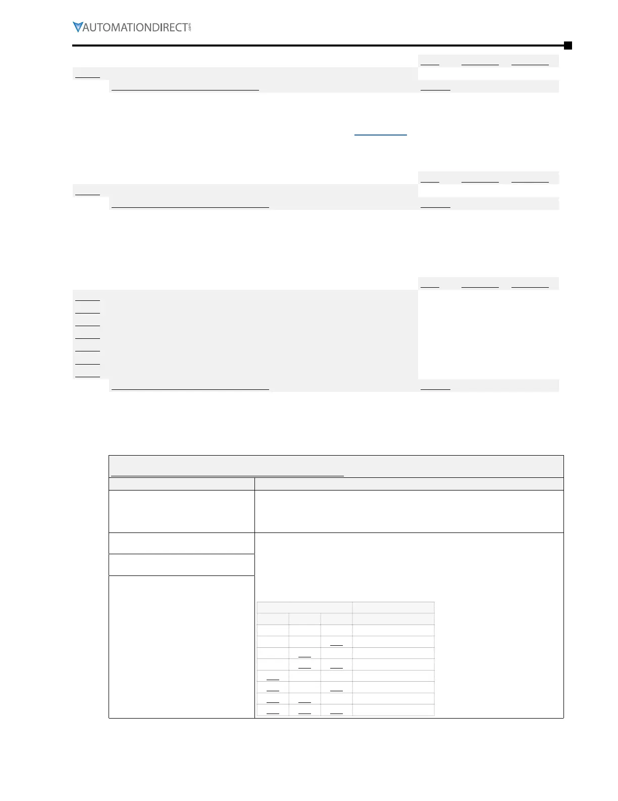
Multi-Function Input Terminal Function Settings (P3.03~P3.16) for Input Terminals DI1~DI16
(abbreviated listiNg; iNcludes oNly settiNgs applicable to pid)
Setting: Function Function Description
0: No function
Setting a Multi-Function Input to 0 will disable that input� The purpose of this
function is to provide isolation for unused Multi-Function Input Terminals�
Any unused terminals should be programmed to 0 to make sure they have
no effect on drive operation.
1: Multi-Speed/PID Multi-Setpoint
bit 1
When settings 1, 2, & 3 are selected and registers P7�06~P7�12 are populated,
the Multi-Function Inputs refer to PID Multi-Setpoints� The SPs are determined
by P7�06~P7�12�
1) In order to use the Multi-PID SPs, P7.06~P7.12 must be set, and P7.00≠0.
2) When all PID Multi-Setpoint inputs are off, the GS4 drive reverts to the PID
Setpoint Source (P7�02)�
PID Setpoint Selection
Bit 3 Bit 2 Bit 1 PID Setpoint
OFF OFF OFF P7�02: SP Source
OFF OFF ON P7�06: Setpoint 1
OFF ON OFF P7�07: Setpoint 2
OFF ON ON P7�08: Setpoint 3
ON OFF OFF P7�09: Setpoint 4
ON OFF ON P7�10: Setpoint 5
ON ON OFF P7�11: Setpoint 6
ON ON ON P7�12: Setpoint 7
2: Multi-Speed/PID Multi-Setpoint
bit 2
3: Multi-Speed/PID Multi-Setpoint
bit 3

 Loading...
