Chapter 4: AC Drive Parameters
Page 4–195
DURApulse GS4 AC Drive User Manual – 1st Ed, Rev A - 10/20/2017
Type Hex Addr Dec Addr
P10.01 Number of Connected Motors
R/W 0A01 42562
Range/Units (Format: 16-bit binary) Default
1~8
1
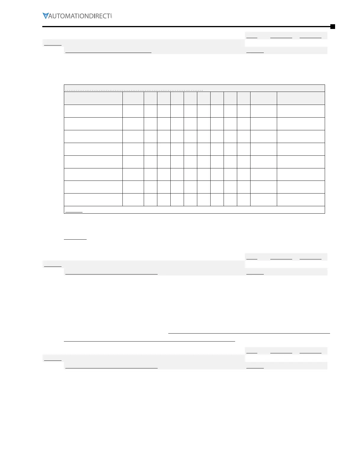
Parameter P10.01 sets the Number of Motors (maximum 8). The number of motors defined in this
parameter will automatically configure multi-function output terminals to the following settings:
Multi-Function Output Terminals on Circulating Motors*
Circulative Control P10.01 01 02 03 04 05 06 07 08
Modes
1,3,5
Modes 2,4
Multi-Function Output
(R1)
P3�17 47 47 47 47 47 47 47 47 Motor 1 Motor 1 on Drive
Multi-Function Output
(R2)
P3�18 48 48 48 48 48 48 48 Motor 2 Motor 1 on AC Line
Multi-Function Output
(R10)
P3�21 49 49 49 49 49 49 Motor 3 Motor 2 on Drive
Multi-Function Output
(R11)
P3�22 50 50 50 50 50 Motor 4 Motor 2 on AC Line
Multi-Function Output
(R12)
P3�23 51 51 51 51 Motor 5 Motor 3 on Drive
Multi-Function Output
(R13)
P3�24 52 52 52 Motor 6 Motor 3 on AC Line
Multi-Function Output
(R14)
P3�25 53 53 Motor 7 Motor 4 on Drive
Multi-Function Output
(R15)
P3�26 54 Motor 8 Motor 4 on AC Line
*NOTE: The order of motors (1~8 or 1~4) is fixed in GS4 firmware, and cannot be changed.
Reducing the number of motors in P10.01 will remove settings associated with outputs R1, R2, &
RO10~RO15 depending on the current number of motors selected in P10.01.
Example: changing P10.01 from 8 motors to 6 motors will automatically change P3.25 from “54:
Mtr 8 On” to “0: No Function,” and P3.24 from “53: Mtr 7 On” to “0: No Function.”
Type Hex Addr Dec Addr
P10.02 Desired Run Time of Each Motor in Minutes
R/W 0A02 42563
Range/Units (Format: 16-bit unsigned) Default
0~65500 min
0
This parameter sets the Desired Run Time of Each Motor in minutes for each of the connected
motors defined in parameter P10.01.
Stopping and then restarting the drive will reset the timer. (If the desired run time is 60 minutes,
and the drive is stopped and restarted at 59 minutes, the active pump will continue to run for
another 60 minutes.)
A value of zero in P10.02 stops timing. In that event, a connected motor that is currently running will
continue to run until a stop command is received by the GS4 drive.
Type Hex Addr Dec Addr
P10.03 Motor Switch Delay Time During Increasing Demand
R/W 0A03 42564
Range/Units (Format: 16-bit unsigned) Default
0�0~3600�0 sec
1�0
As demand increases, this parameter defines the Delay Time in seconds from turn-off of the
connected motor to turn-on of the next motor in the sequence.
When the connected motor elapsed Run Time equals the value in P10.02, the GS4 drive turns off
that motor, and Delay Time begins to increment.
When the Delay Time in parameter P10.03 has elapsed, the GS4 drive will turn on the next
connected motor in the sequence.

 Loading...
