Chapter 4: AC Drive Parameters
Page 4–203
DURApulse GS4 AC Drive User Manual – 1st Ed, Rev A - 10/20/2017
terMinal sPeciFications For gs4-06tr (oPtional six-relay outPut card)
Terminal Specifications for GS4-06TR (Optional Six-Relay Output Card)
Part # Terminals Description
GS4-06TR
R10~R15
RO10~RO15
Refer to P3�21~P3�26 for Multi-function Output selection
Resistive Load: 5A(NO) @ 250VAC
5A(NO) @ 30VDC
In ductive Load (COSØ 0�4): 2A(NO) @ 250VAC
Six SPST relay outputs
Rxx = separate common for each relay
ROxx = normally open output
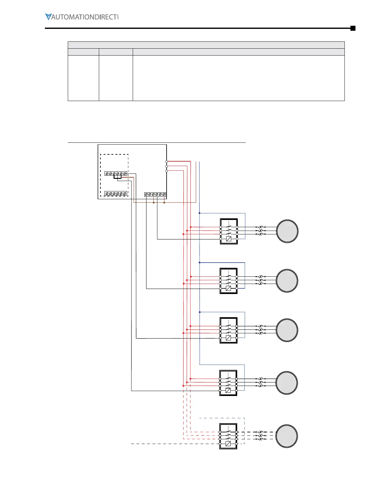
wiring diagraMs For cyclical PuMP control
tiMe circulation control (P10.00=1) – wiring
(Maximum of eight motors connected; only one runs at a time)
M1
M2
M3
M4
L
N
U V W
R2O
R2C
R2
R1O
R1C
R1
GS4 DRIVE
GS4-06TR
RO13
R13
RO14
R14
RO15
R15
R12
RO12
R11
RO11
R10
RO10
Contactor
Contactor
Contactor
Contactor
O/L
O/L
O/L
O/L
Multi-function output R1
P3.17=47 (motor 1)
Multi-function output R2
P3.18=48 (motor 2)
Multi-function output R10
P3.26=49 (motor 3)
GS4-06TR option card
Multi-function output R11
P3.27=50 (motor 4)
GS4-06TR option card
M8
O/L
...up to 8 motors

 Loading...
