Chapter 5: Serial Communications
Page 5–7
DuRApulse GS4 AC Drive User Manual – 1st Ed, Rev A - 10/20/2017
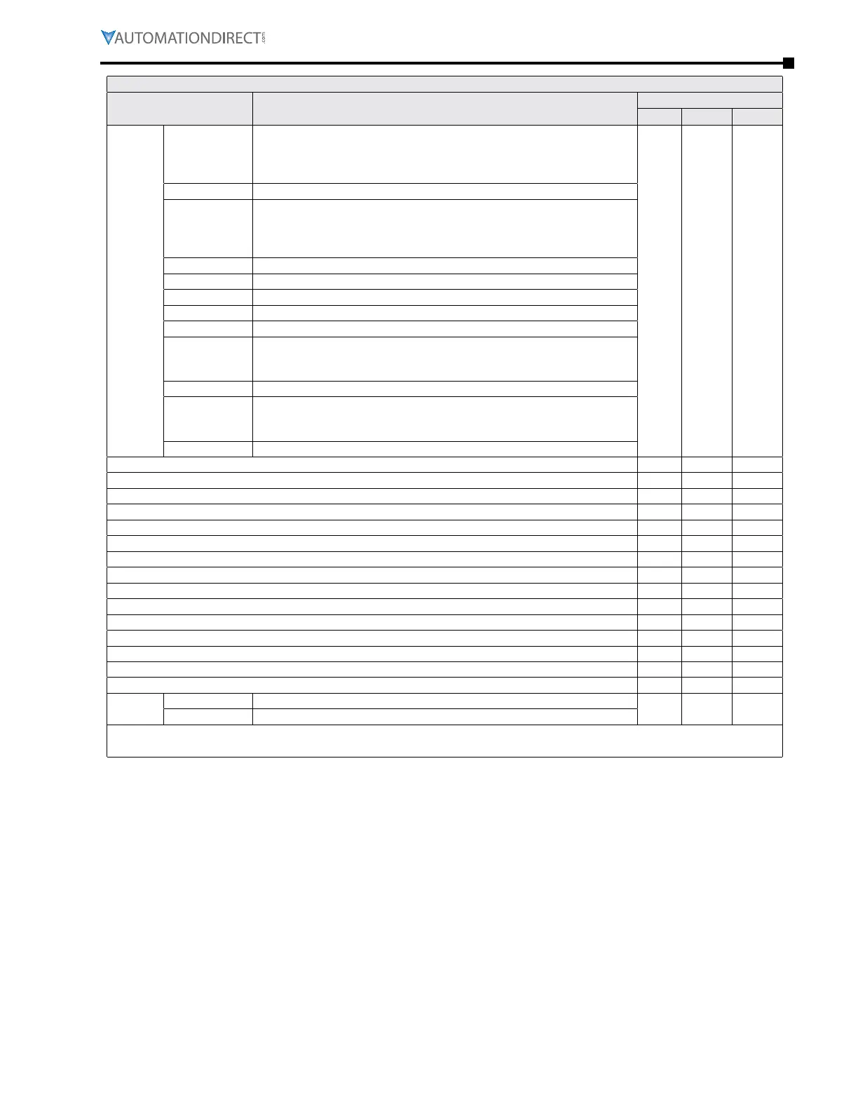
GS4 Status Addresses (continued from previous page)
Description Range
Modbus Address
Hex Dec Octal
Status
Monitor
2
Bit 0,1
0: Stop
1: Decelerate during the drive stopping
10: The drive standby
11: Run
2101 48450 20401
Bit 2 1: JOG active
Bit 3,4
0: FWD
1: REV to FWD
10: FWD to REV
11: REV
Bit 5 Reserved
Bit 6 Reserved
Bit 7 Reserved
Bit 8 1: Source of frequency by communication
Bit 9 1: Source of frequency by AI
Bit 10
1: Source of operation by communication
(If Keypad Stop is enabled (P3�00, P3�01 = 1,3,5), this bit will remain “1”
even if the source of operation is not communication�)
Bit 11 1: Parameters have been locked
Bit 12
Running Status
0: Drive stopped
1: Drive running (including Standby)
Bit 13 to Bit 15 Reserved
Frequency command F (xxx�x) * 2102 48451 20402
Output Frequency H (xxx�x) 2103 48452 20403
Output Current A (xxx�x) 2104 48453 20404
DC-BUS Voltage U (xxx�x) 2105 48454 20405
Output Voltage E (xxx�x) 2106 48455 20406
Multi-Speed or PID Inputs current Step Number 2107 48456 20407
Active Warning 2108 48457 20410
DI6 Counter Value (must set P3�44) 2109 48458 20411
Power Factor angle ( cos θ) 210A 48459 20412
% Load 210B 48460 20413
Motor Actual RPM 210C 48461 20414
reserved 210D 48462 20415
reserved 210E 48463 20416
reserved 210F 48464 20417
reserved 2110 48465 20420
Error/
Warning
Low Byte Active Error [2100h = Active Error/Fault]
2118 48473 20430
High Byte Active Warning [2108h = Active Warning]
* If frequency command is greater than the Drive Maximum Output Frequency (P0.04), the GS4 drive will
accelerate to the Drive Maximum Output Frequency, as defined in (P0.04).

 Loading...
