Chapter 8: GSLogic Introduction
Page 8–5
DuRApulse GS4 AC Drive User Manual – 1st Ed, Rev A - 10/20/2017
5) Please note when using WPR (Write to Drive Parameters) commands, values may be
modified up to a maximum of 10
9
times. More than this number of writes will result in a
memory write error. The calculation of modifications is based on whether the entered value
has been changed. If the entered value is left unchanged, the modification count will not
increase. But if the entered value is different from before, the modification count will
increase by one.
The parameters in the following table are exceptions, and can be written to an unlimited
number of times. The FREQ instruction is also an exception to this.
Parameter Description
P2.11
Control Mode
P1.01~P1.08
1st~4th Acc/Dec Time
P3.42
Multi-Function Input Contact Selection
P3.43
Multi-Function Output Contact Selection
P8.20~P8.39
PLC buffer 1~20
P7.16
Upper Limit for Integral Time
P7.18
PID Output Frequency Limit
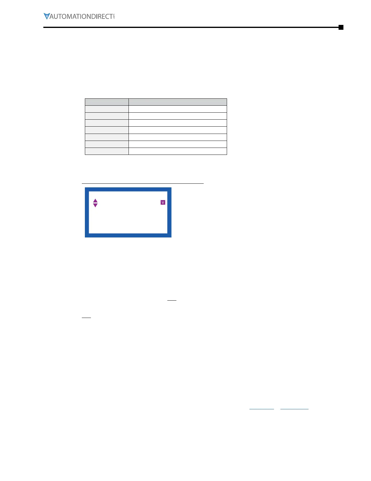
6) When parameter P8.00 is set to 28 (User Display = PLC D1043 Value), the GS4 keypad
displayed value will be the value of PLC register D1043 (see the 3rd line in the figure below).
Digital Keypad GS4-KPD Can Display 0~65535
F 60.00 Hz
H 0.00 Hz
u 540.0 Vdc
PLC/STOP
AUTO
JOG
23:21:13
7) In the PLC Run and PLC Stop modes, the parameter P9.08 cannot be set to 9 or 10 (cannot
be reset to factory defaults). PLC must be in Disable mode for this. A power cycle is needed
after setting P9.08 = 9 or 10.
8) The PLC memory will be cleared and the program erased from the PLC when parameter
P9.08 is set to 6.
9) When the PLC controls the GS4 drive operation, control commands will be entirely
controlled by the PLC, and will not be affected by the setting of parameter P3.00 or P3.01.
10) When the PLC controls the GS4 drive frequency commands, the commanded frequency will
not be affected by parameter P4.00, P4.01, or the Hand ON/OFF configuration.
11) The use of certain registers will disable the drive’s control of the drive output frequency.
The instructions and registers that transfer control of the drive output to the PLC are: FREQ,
M1040, M1025, M1026, and M1027. See P9.34 for details about what the PLC controls.
12) While the PLC is enabled and controlling the GS4 drive operation, if the keypad Stop button
is pressed, an “Fstp” error will be triggered and cause the drive output to stop if P3.00 or
P3.01 is set to 1, 3, or 5. A Special Function Relay (M1005) in the PLC will also be triggered.
The PLC will continue to scan through the ladder code. When the keypad Stop/Reset is
pressed again, the drive control is returned to the PLC.
13) The corresponding drive parameter Multi-Function Inputs and Outputs will be disabled
when the PLC ladder program contains external terminal usage X and Y registers.
(See GS4 AC Drive to PLC Input/Output Cross Reference tables, page 8–8 & page 8–8.)

 Loading...
