20. Scheduled operations
Both laser clusters ar e cooled by a liquid t hermal system. T his s ystem is built up by s ingle circuits, consisting of fan, radiator and
pump. There are two such single systems on each laser cluster. The pump is directly installed to t he clusters; a thermal conductive
compound is used between the pump and the cluster to ensure good thermal connection.
In order to access the laser clusters, PC B main including she et me tal brackets an d main PSU should be re-
moved, following the ste ps in Chapter 20 , “Technical Op erations”.
The procedure is identical for both the las er c lusters.
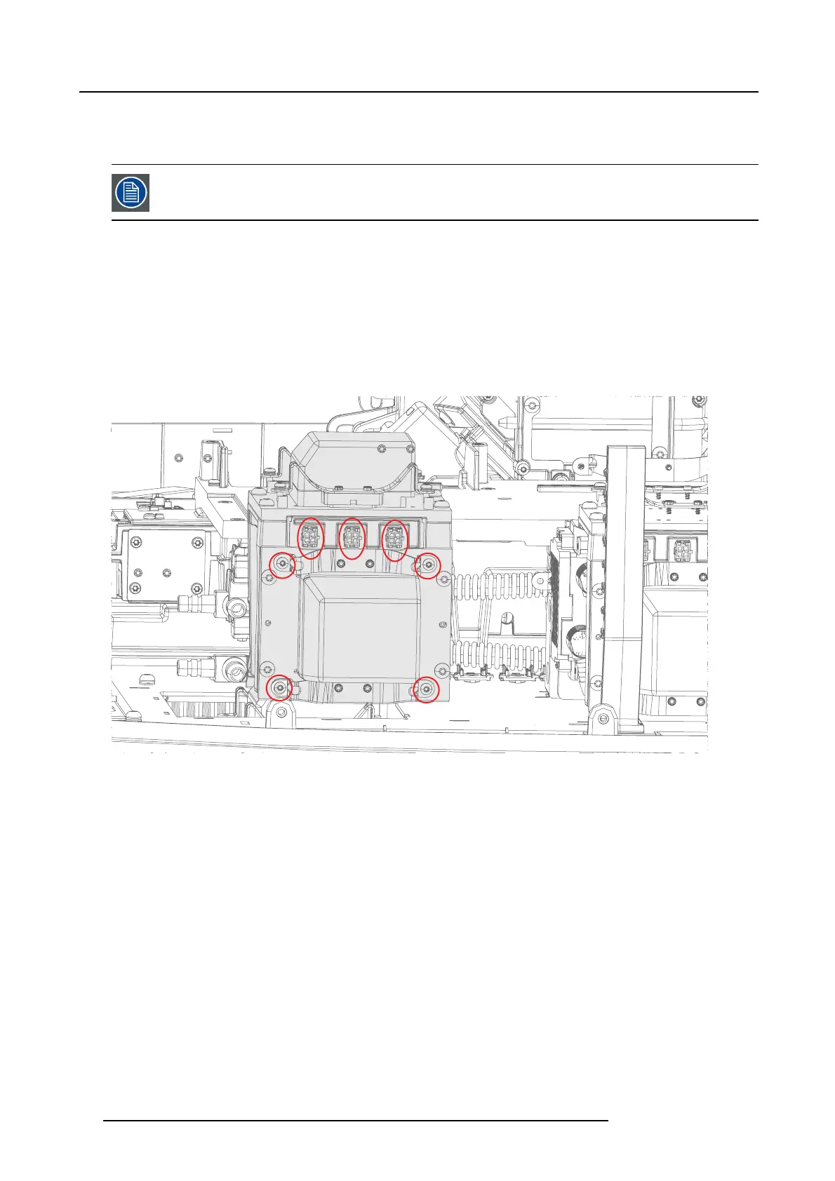
1. 1. Disconnect 2x3 power connectors on each laser bank , indicated by red ovals on the picture below
2. 2. Rem ove 4+4 screws (T10 M3x10 w/w asher), securing the liquid cooling pumps to each B lue laser c luster. Us e an X -sequence
(diagonal sequence) when loosening the screws.
Image 20-17
3. 3. It may be easier to release the cool
ing pumps if the copper s urface of laser cluster has been pre-heated. Use an adjustable
heat gun set to 80°C - 90°C (176°F). Preheat the pump and c opper plate for approximately 2 m inutes. .
4. 4. When the co pper plate has reached the w anted temperature, carefully pull the bracket in order to release the pump from the
laser Cluster.
92 723–0016 F90 01/12/2017