20. Scheduled operations
Image 20-18
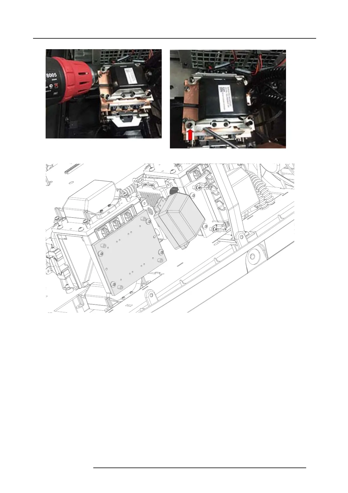
Image 20-19
Image 20-20
5. 5. Loosen , but do not unscrew fully, the two screws (Tx20 M50x45) and slide off the locking clamp and r emove the old laser
cluster. It is recommended to hold the
cluster with one h and while loosen a nd removing the locking clamp, to avoid that the
cluster falling to the bottom.
6. 6. Position the new laser cluster to the Laser Interface. Ensure that the cluster is properly in place. T he cluster will “fall in” to a
track, and it will not be possible to rotate it vertically when it is in cor rect position. The line between the c luster and the interface
will be narrow and pa ralell. Tighten up the clamps on each side, and ensure correct position and fit also for the clamps.
Note: All clamp screws m ust be tighten with a 3,1Nm torque.
723–0016 F90 01/12/2017
93