105
V2.6 | 8/30/2022 | 1120758
7.10 Category: DigitalIOControl
The Digital I/O chapter covers the features required to control the general Input and Out-
put signals of the device.
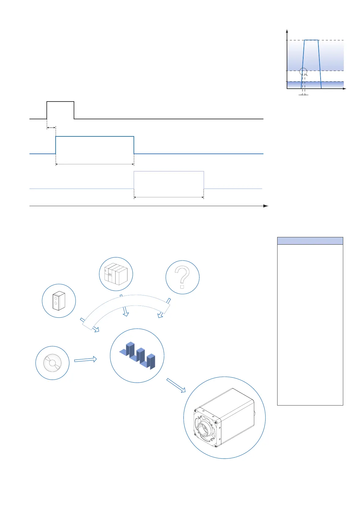
Trigger (Line Selector → Line 0 / Line 1) (General Information)
Trigger signals are used to synchronize the camera exposure and a machine cycle or, in
case of a software trigger, to take images at predened time intervals.
Trigger (valid)
Exposure
Readout
Time
A
B
C
Different trigger sources can be used here.
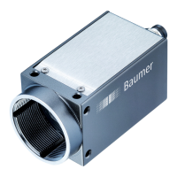
Trigger Source (Examples of possible trigger sources)
p
h
o
t
o
e
l
e
c
t
r
i
c
s
e
n
s
o
r
t
r
i
g
g
e
r
s
i
g
n
a
l
p
r
o
g
r
a
m
m
a
b
l
e
l
o
g
i
c
c
o
n
t
r
o
l
l
e
r
o
t
h
e
r
s
s
o
f
t
w
a
r
e
t
r
i
g
g
e
r
H
a
r
d
w
a
r
e
t
r
i
g
g
e
r
Each trigger source must be activated separately. When the trigger mode is activated, the
hardware trigger is activated by default.
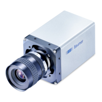
high
low
U
11V
30V
start active
trigger
A - Trigger delay
B - Exposure time
C - Readout time
Trigger Delay:
The trigger delay is a
exible user-dened delay
between the given trigger
impulse and the image
capture. The delay time
can be set between 0.0
μs and 2.0 s in increments
of 1 μs. Where there are
multiple triggers during the
delay, the triggers will also
be stored and delayed. The
buffer is able to store up to
512 trigger
signals during the delay.
Your benets:
▪ No need for an external
trigger sensor to be perfect-
ly aligned
▪ Different objects can be
captured without hardware
changes