40
V2.6 | 8/30/2022 | 1120758
5. Pin Assignment / LED-Signaling
5.1 VLXT(.I) (.EF) (.JP) (10GBASE-T) / VLXN.I.JP (5GBASE-T)
5.1.1 Data Interface
Notice
You can also operate the camera on a slower data interface than 10GigE. This reduces
the performance.
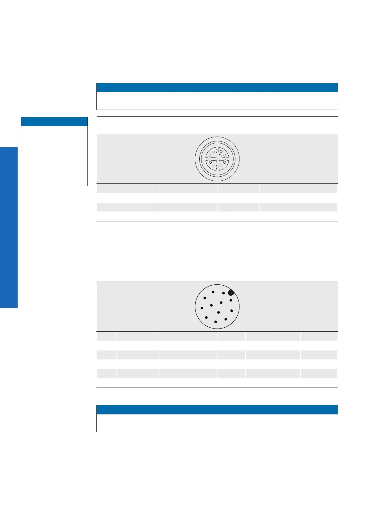
Ethernet
(SACC-CI-M12FS-8CON-L180-10G)
2
18
7
6
5
4
3
1 MX1+ 5 MX4+
2 MX1- 6 MX4-
3 MX2+ 7 MX3-
4 MX2- 8 MX3+
5.1.2 Power and Process Interface
Power supply / Digital-IO
(SACC-CI-M12MS-12CON-L180)
wire colors of the connecting cable
*
(ordered separately)
8
9
10
11
12
5
3
1
4
2
6
1 Power Vcc brown 7 OUT3 (Line6) black
2 GND (Power) blue 8 RS232 TxD (Line2) grey
3 IN1 (Line0) white 9 OUT4 (Line7) red
4 OUT1 (Line4) green 10 RS232 RxD (Line3) violet
5 IN2 (Line1) pink 11 GND (IO) grey-pink
6 OUT2 (Line5) yellow 12 Power (IO) red-blue
*)
shielded cable needs to be used
Notice
Max.Voltage levels RS232 TxD, RS232 RxD line +-15 V. The RS232 interface is contol-
lable by the UART1 value of boSerialSelector.
Notice
The unit is to be con-
nected only to inter-
nal Ethernet networks
without exiting a facili-
ty and being subjected
to Telecom Network
Voltages (TNVs).