45
V2.6 | 8/30/2022 | 1120758
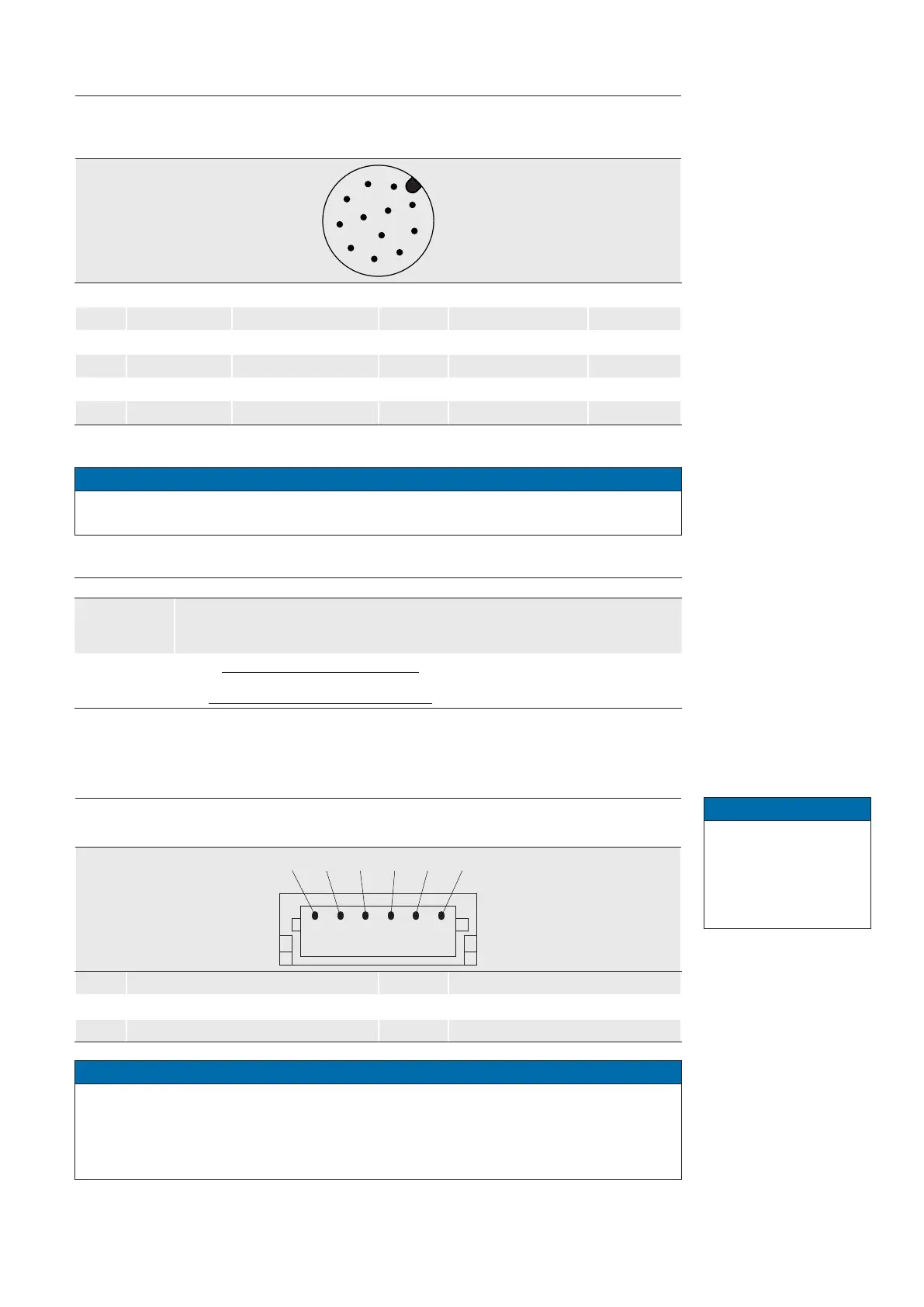
5.2.3 Power and Process Interface
Power supply / Digital-IO
(SACC-CI-M12MS-12CON-L180)
wire colors of the connecting cable
*
(ordered separately)
8
9
10
11
12
5
3
1
4
2
6
1 Power Vcc brown 7 OUT3 (Line6) black
2 GND (Power) blue 8 RS232 TxD (Line2) grey
3 IN1 (Line0) white 9 OUT4 (Line7) red
4
OUT1 (Line4) green
10
RS232 RxD (Line3) violet
5
IN2 (Line1) pink
11
GND (IO) grey-pink
6
OUT2 (Line5) yellow
12
Power (IO) red-blue
*)
shielded cable needs to be used
Notice
Max.Voltage levels RS232 TxD, RS232 RxD line +-15 V. The RS232 interface is contol-
lable by the UART1 value of boSerialSelector.
Power Supply
Power V
CC
12 V ... 24 V (-15 % ... + 20 % ) (Power consumption: max. 9.6 W)
Power (IO)
For UL conform installations: 12 V (- 20 %) … 24 V (+ 20 %)
For not UL conform installations: 12 V (- 20 %) … 48 V (+ 10 %)
5.2.4 UART0Interface(≥Release3only)
UART0 Interface
(JST BM06B-SRSS-TB)
1 Power (UART0) 4 UART TxD
2 GND (UART0) 5 not connected
3 UART RxD 6 not connected
Notice
Serial interface voltage level for UART0 TxD and RxD: 0 V (logical 0) ... 3.3 V (5V toler-
ant) (logical 1).
This interface is controllable by UART0 value of boSerialSelector and is used to control
optical components.
Class 2 per NEC / Pro-
tection Class III
The device is intended
to be supplied from an
isolated Limited Energy
Source per UL61010-1,
3rd ed cl. 9.4 or Lim-
ited Power Source per
UL60950-1 or Class 2
per NEC.
Notice
Please observe the
instructions and notes
in the technical docu-
mentation of the re-
spective lens!