3-123
Confidential
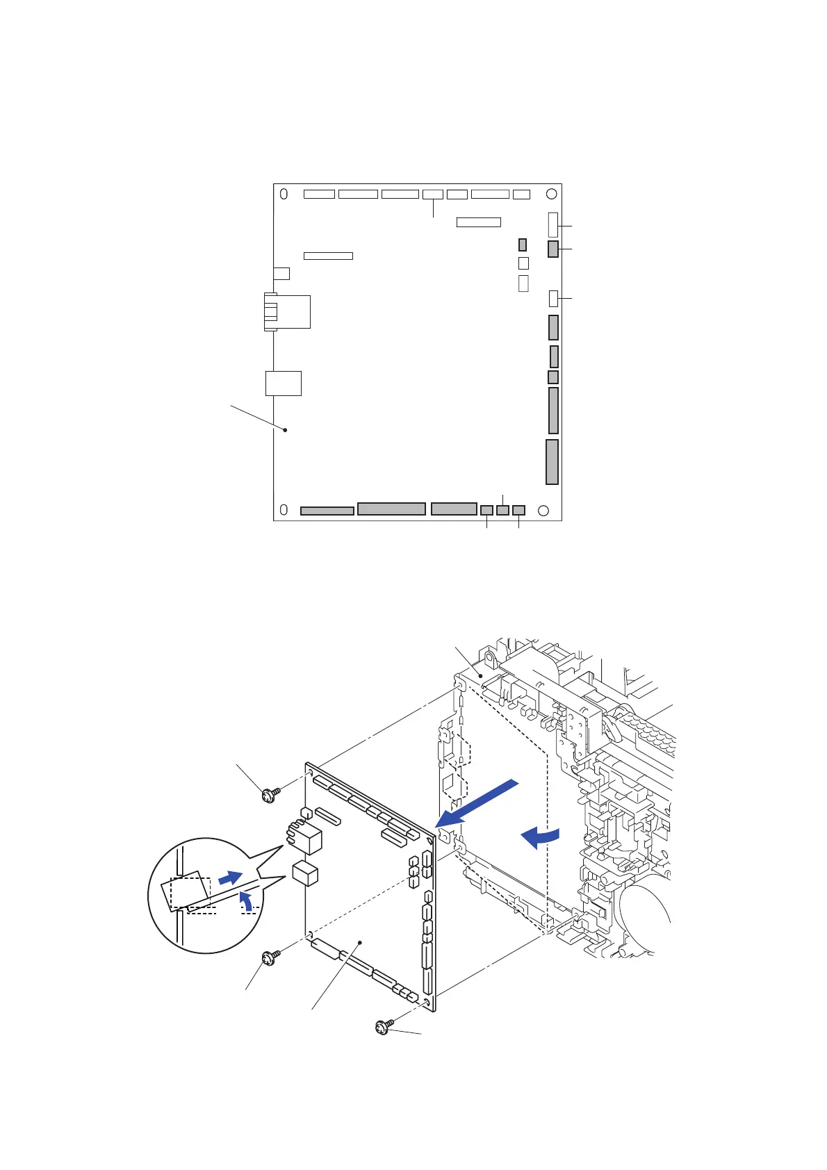
8.51 Main PCB ASSY
(1) Disconnect the ten Connectors (CN1, CN4, CN5, CN6, CN9, CN10, CN12, CN13, CN14
and CN20) and three Flat cables (CN2, CN3 and CN7) from the Main PCB ASSY.
Fig. 3-172
(2) Remove the three Taptite cup S M3x8 SR screws to remove the Main PCB ASSY from the
Side frame L ASSY.
Fig. 3-173
CN30
CN22
CN19
CN15
CN1 1
CN4
CN3 CN2
CN1 CN6
CN5
CN29 CN28 CN26 CN23
CN8
CN21
CN27
CN20
CN14
CN25
CN24
CN16
CN9
CN13
CN12
CN10
CN7
CN17
Main PCB ASSY
Side frame L ASSY
Taptite cup S M3x8 SR
Taptite cup S M3x8 SR
Taptite cup S M3x8 SR
Main PCB ASSY
<Left side>
2a
2b
2a
2b

 Loading...