Confidential
2-19
<Installing Procedure>
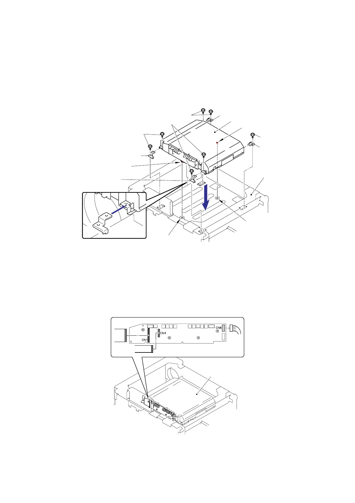
(1) Assemble the Laser unit with the four Scanner holders and seven cup S M3x6 SR Taptite
screws.
Note:
When assembling the Laser unit with the Scanner holders, ensure to put the positioning
boss of the Laser unit into the positioning hole referring to the figure below.
Fig. 2-28
(2) Connect the two flat cables (CN1, CN4) and one connector (CN8) into the Laser unit.
Note:
When connecting the flat cable(s), do not insert it at an angle. After insertion, check that
the cable is not at an angle.
Fig. 2-29
Scanner holder
Taptite, cup S M3x6 SR
Laser unit
Scanner holder
Frame unit
Taptite, cup S M3x6 SR
Taptite, cup S M3x6 SR
Scanner holder
Scanner holder
Taptite, cup S M3x6 SR
<Front>
Laser unit
<Front>
Positioning boss
Positioning boss
Positioning hole
Positioning hole

 Loading...