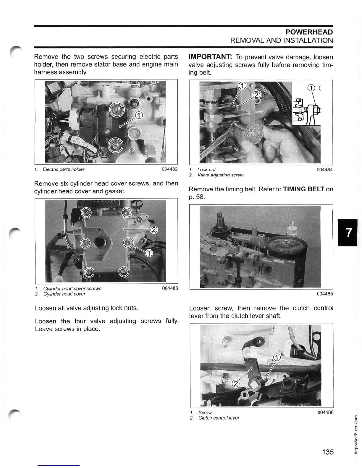
Remove the two screws securing electric parts
holder, then remove stator base and engine main
harness
assembly.
1.
Electric parts holder
004482
Remove six cylinder head cover screws, and then
cylinder head cover and gasket.
1. Cylinder head cover screws
004483
2.
Cylinder head cover
Loosen all valve adjusting lock nuts.
Loosen the four
valve adjusting screws fully.
Leave screws
in
place.
POWERHEAD
REMOVAL AND INSTALLATION
IMPORTANT:
To
prevent valve damage, loosen
valve
adjusting screws fully before removing tim-
ing
belt.
1. Lock nut
004484
2. Valve adjusting screw
Remove the timing belt. Refer to TIMING BELT
on
p. 58.
004485
Loosen screw, then remove the clutch control
lever
from the clutch lever shaft.
1.
Screw
004486
2.
Clutch control lever
135
I
E
o
o
~
><
~
Qj
~
i:i
E