EasyManuals Logo

Bruker NMR BSMS System User Manual

Bruker NMR BSMS System
234 pages
To Next Page IconTo Next Page
To Previous Page IconTo Previous Page
Page #155 background imageLoading...
Page #155 background image
SPB
H172203_1_001 155 / 234
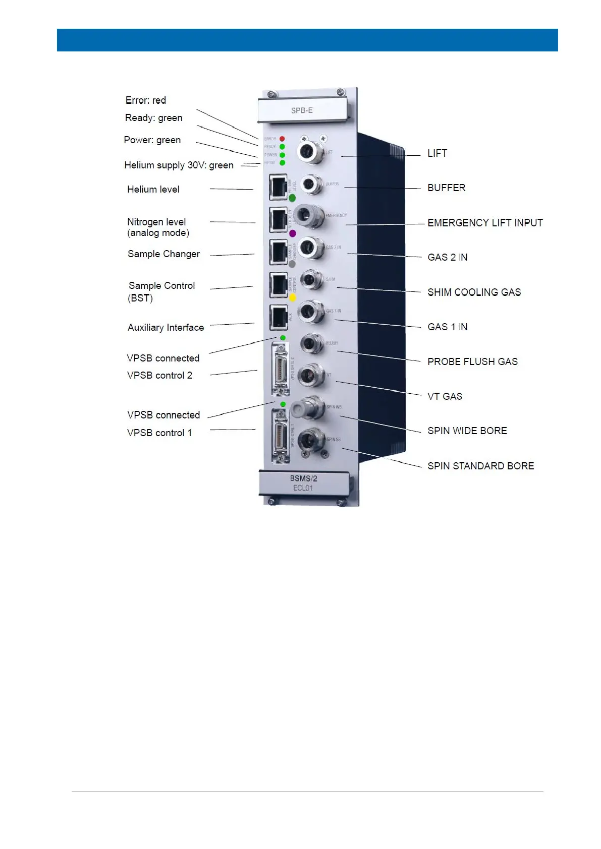
Figure14.4: Front View of a SPB-E
Ready LED
This LED is active as soon as the FPGA design is loaded and valve and sensor inter- faces
are active.
Power LED
Indication that the SPB is correctly powered.
HE30V LED
Indication that the galvanically isolated power supply for the helium level measurement is
available.
VPSB connected LED
Whenever a VPSB is connected and initialized correctly, the LED above the connectors
labeled VPSB CTRL will be switched on. This can used for diagnostic purpose.

Table of Contents

Questions and Answers:

Question and Answer IconNeed help?

Do you have a question about the Bruker NMR BSMS System and is the answer not in the manual?

Bruker NMR BSMS System Specifications

General IconGeneral
BrandBruker
ModelNMR BSMS System
CategoryChassis
LanguageEnglish