Section 1 — Introduction
1-4 Part No. 750-363
1.2.5. Variable Speed Drive
Modulating combustion air fan speed is controlled by a Variable
Speed Drive mounted inside the front casing below the Falcon control
panel.
1.2.6. Component/Connection Locations
Figure 1-5 shows the CFLC component orientation and heat flow
path. The return water connections are at the lower vessel and the
hot water outlet is at the top of the boiler.
Figure 1-6 shows the locations of the safety valve and air vent
connections. Figure 1-7 shows the location of the return water
temperature sensor.
The stack is connected on the right side of the boiler when facing the
front. The flue gas duct sizes may be reduced at the vent connection.
See also Section 3,
Stack and Intake Vent Sizing and Installation.
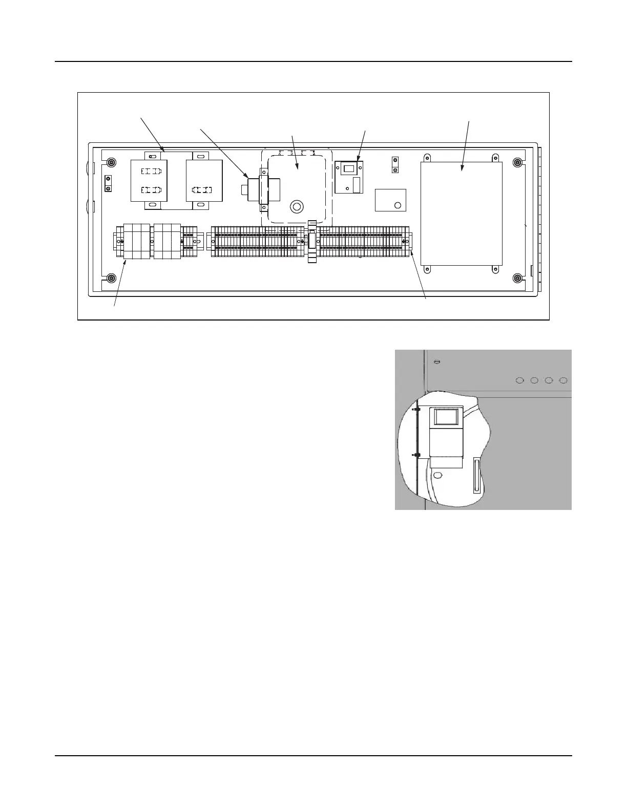
Figure 1-3 Control panel interior
IGNITION TRANSFORMER
(FAR SIDE)
FALCON CONTROLLER, HYDRONIC
WATER LEVEL
CONTROL - LWCO
TRANSFORMER, 115v/25v
TRANSFORMER, 460/230/208V PRI, 115 V SECONDARY,
350VA, FUSED TOP
TERMINAL TRACK
FUSE, 9 AMP
Figure 1-4 VSD (cutaway view)