Appendix C Gas Valve
C-26
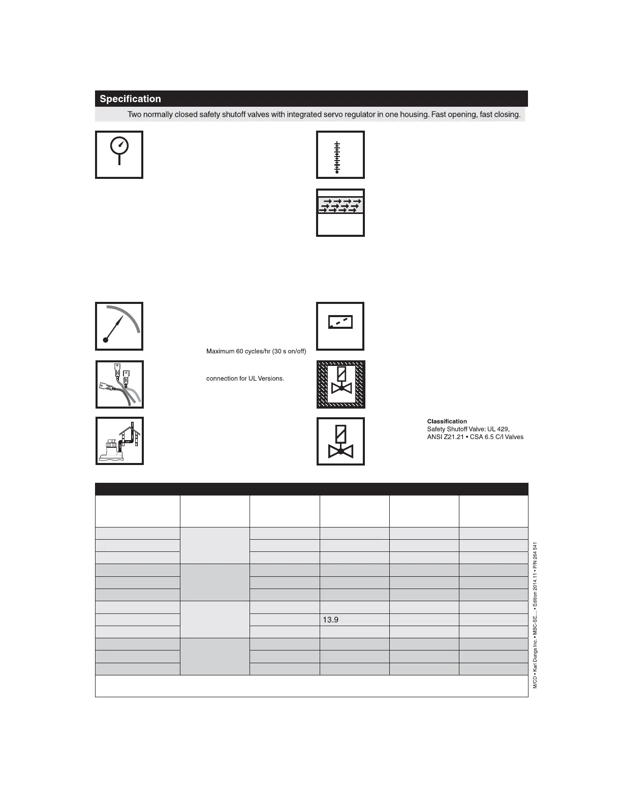
Safety Valve Max. Oper ating
Pressure
MOP = 5 PSI (360 mbar)
Regulator Oper ating P ressure
Ratings
S22/S82: p
in
= 6 - 147 in. W.C.
S302: p
in
= 14 - 147 in. W.C.
S02: p
in
= 4 - 41 in. W.C.
N: p
in
= 4 - 41 in. W.C.
Regulator Outlet P ressure R anges
S22: p
out
= 1.6 - 8 in. W.C.
S82: p
out
= 2 - 32 in. W.C.
S302: p
out
= 12- 122 in. W.C.
S02: p
out
= 0 ± 0.8 in. W.C.
N: p
out
= 0 ± 0.8 in. W.C.
Ambient Temperature (CSA)
-40 °F ... +140 °F
(-40 °C … +60 °C)
Ambient Temperature (UL)
+5 °F ... +140 °F
(-15 °C … +60 °C)
Gases
Dry, natural gas, propane, butane;
other noncorrosive gases. A “dry” gas
has a dew point lower than +15 °F and
its relative humidity is less than 60 %.
Materials in contact with Gas
Housing: Aluminium, Steel, free of
nonferrous metals. Sealings on valve
seats: NBR-based rubber.
Electrical Ratings
110 - 120 VAC / 50 - 60 Hz;
24 VAC / 50 - 60 Hz; 12 VDC, 24 VDC
Operating time
100 % duty cycle
Cycle Rate
Filter
installed in the housing upstream V1
50 micron
of Valve V1 and V2
Closing Time (Valve 1 & Valve 2)
< 1 s
Opening Time
(Valve 1 & Valve 2)
< 1 s
MBC-
[PSI]
[V] [A]
[Hz ] [VA ]
Gas
°F
0
-40
+150
Electrical Connection
DIN-connector with 1/2” NPT conduit
Order separately for CSA Versions
Power Consumption with all coils
energized
see table below
NEMA
Enclosure Rating
NEMA Type 12 / IP54
Vent Li miting De vice and Vent Li ne
Connection
The MBC has an internal, factory
installed vent limiter re ANSI Z21.18/
CSA 6.3. Venting required unless
otherwise accepted by the authority
having jurisdiction.
Power Consumption Table
Valve Body Size Rated voltage Inrush P
max.
[VA] for t = 3 s
Inrush current
peak (A)
Holding P
max.
[VA] Operation
Recommended
power of supply
transformer ( VA)
MBC 1000
12 VDC
140 20.1 16 DC battery
MBC 2500 160 20.1 20 DC battery
MBC 4000 ––––
MBC 1000
24 VDC
130 13.4 16 DC battery
MBC 2500 160 13.4 20 DC battery
MBC 4000 200 2.8 30 DC battery
MBC 1000
24 VAC*
120 14.7 20 250
MBC 2500 160
20 300
MBC 4000 ––––
MBC 1000
120 VAC*
120 3.1 16 250
MBC 2500 180 3.0 20 300
MBC 4000 250 2.4 25 300
*Power supply should compensate for the inrush current, and wire gauge should be considered. In order to absorb voltage
spikes during inrush, an electrolytic capacitor (4700 μF) between MBC and transformer is recommended.