Section 1 — Introduction
Part No. 750-363 1-3
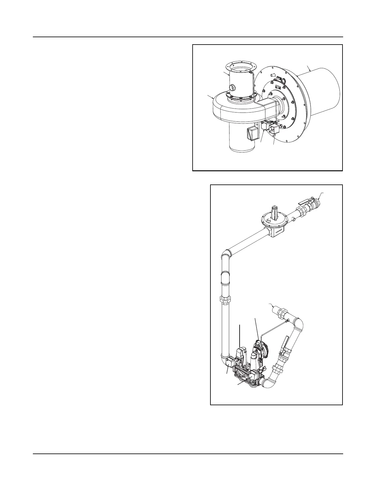
1.2.2. The Burner
The burner utilizes a premix venturi, self-regulating
fuel train, variable speed blower modulation, and
Fecralloy metal fiber burner head.
Modulating combustion air fan provides 5:1
turndown.
Combustion canister of the burner is constructed of a
Fecralloy-metal fiber for solid body radiation of the
burner flame, which provides low emissions.
At maximum firing rate, the sound level of the burner
is less than 85 dBA, measured in front of the boiler at
a distance of 3 feet.
Room air for combustion is standard (combustion air
filter provided).
A direct vent combustion air adapter kit is available.
Refer to Installation and Parts sections in this manual
for options and details.
1.2.3. Burner Gas Train
The gas train assembly is provided in accordance with UL
certification and complies with ASME CSD-1. The gas train
assembly is factory assembled and wired, consisting of the
following components:
A. Low Gas Pressure Switch - manual reset
B. High Gas Pressure Switch - manual reset
C. Single body, dual safety motorized shut-off valves
with POC and regulating actuator
D. Manual Shutoff Butterball Valve
E. Regulator (optional, based on gas supply pressure)
F. Test cocks
1.2.4. Controls
The Falcon hydronic control is an integrated burner
management and modulation control with a touch-screen
display/operator interface.
The controller is capable of the following functions:
• Two (2) heating loops with PID load control.
• Burner sequencing with safe start check, pre-purge, pilot
ignition, and post purge.
• Electronic ignition.
• Flame Supervision.
• Safety shutdown with time-stamped display of lockout
condition.
• Variable speed control of the combustion fan.
• Supervision of low and high gas pressure, air proving, stack
back pressure, high limit, and low water.
• First-out annunciator.
• Real-time data trending.
• (3) pump/auxiliary relay outputs.
• Modbus communication capability.
• Outdoor temperature reset.
• Remote firing rate or setpoint control
• Setback/time-of-day setpoint
• Lead/Lag for up to 8 boilers
CAPS
HAPS
VENTURI
BURNER CANISTER
BLOWER
ASSEMBLY
Figure 1-1 Burner Assembly
GAS INLET
TO VENTURI
A
B
C
E
E
F
Figure 1-2 Gas Train (8000 shown)
D