Section 2 — Installation
Part No. 750-363 2-19
2.10.1 Condensate tank setup options
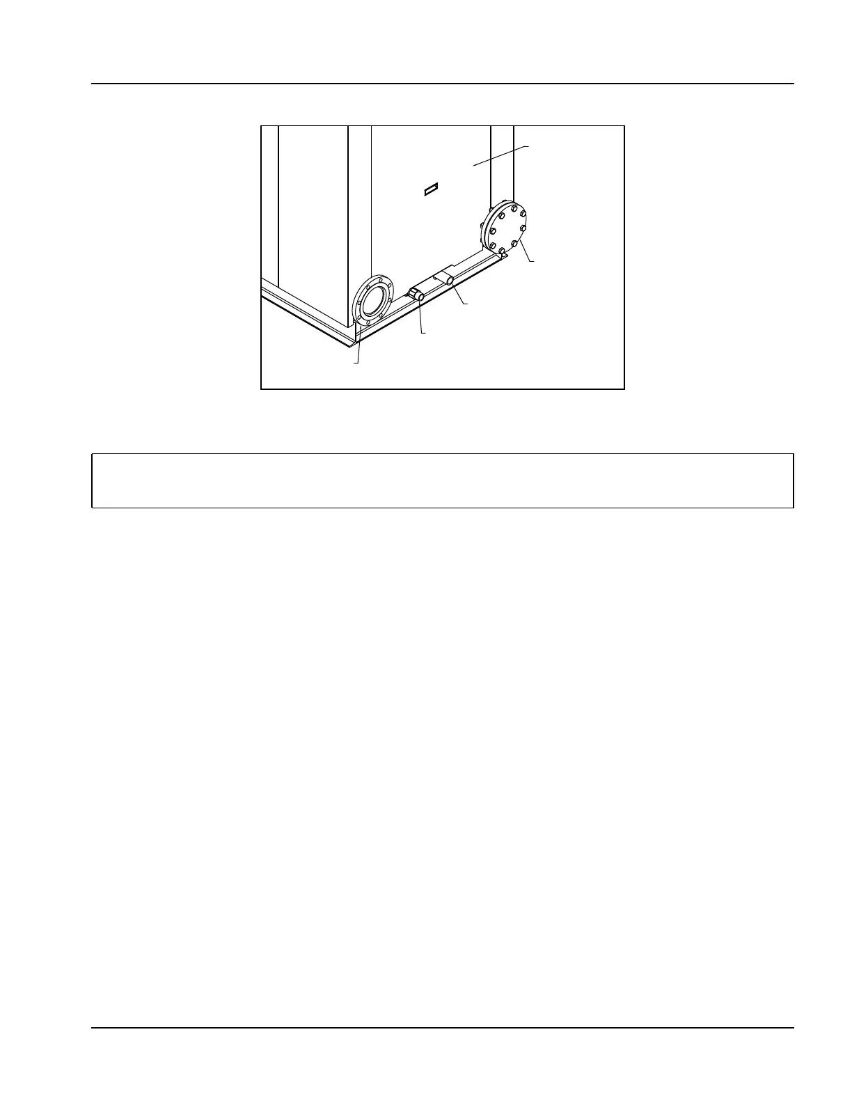
(1) Condensate direct to drain - The condensate is piped directly to a drain through the piping and water
trap supplied during installation (see Figure 2-10).
Piping is to be a minimum of 1-1/4” NPT.
(2) Condensate to treatment tank - The condensate is held in a condensate tank(s) under or near the boiler.
The condensate is neutralized as it passes through a bed of granular material. The neutralized condensate
is then piped to the drain.
• To install the system, assemble the tank and fittings per instructions supplied with tank. Neutralization media are
already installed in tank.
• For CFLC 4000/5000 the tank must be installed external to the boiler (Figure 2-11). For sizes 6000-12000 the
tank(s) may be mounted internally or externally.
• Install the condensate tank cover and connect tank to boiler condensate discharge.
Pipe to an appropriate drain.
Figure 2-10 Condensate Piped Direct to Drain
Note: To ensure compliance with regulations, it is important to contact the responsible authorities prior
to the planning and execution of the boiler installation. Condensate flow of 20 to 80 GPH can be
expected depending on boiler size and return water temperature.
COLD WATER RETURN
CONDENSATE DRAIN
DRAIN
WARM WATER RETURN
BOILER REAR
A CONDENSATE TRAP
IS PIPED WITHIN THE
BOILER.