Appendix E Falcon Lead Lag
E-11
6.4 - Connecting to a Building Energy Management System (EMS)
A Falcon lead lag network may be connected to a building EMS by several means:
• Discrete contact for remote enable - allows a building EMS to send a remote lead lag
system enable signal to the Falcon lead lag Master. To use, connect the signal source to
terminals 24 and 25 on the Master host and remove the jumper there. Jumpers may
stay in place on the remaining slave boilers.
• Analog 4-20mA input for remote setpoint (hot water only) - For remote setpoint
operation, connect a 4-20mA set point signal at terminals 26 and 27 on the Master
host. Go to lead lag configuration parameters (advanced settings) and under Central
Heat parameters change ‘Setpoint Source’ to S2. Set the Master host boiler’s demand
switch to REMOTE.
• Modbus - The Falcon’s Modbus communication capabilities allow the transfer of
information between the lead lag network and a building EMS for purposes of remote
system monitoring or data acquisition. Connection to the lead lag Modbus network is
made at control panel terminals 41 and 42 on each boiler (connected to the Falcon
display’s COM2 terminals). Refer to specific boiler wiring diagram.
An additional use of Modbus is for remote enable/remote setpoint operation. These
features can be implemented via Modbus as an alternative to using the hard contacts as
described above.
See the appendix to this document for Modbus registers and additional information.
Also see manual 750-308 Falcon Modbus Communication (included as an appendix
to the ClearFire boiler manual) for a complete description of Modbus features.
7- COMMISSIONING
Before commissioning the system, ensure all network wiring and sensor connections have been
made according to the above instructions.
Begin with all boilers’ demand switches in the OFF position.
All CC-Blower power switches should be ON.
7.1 - Lead Lag Master Configuration
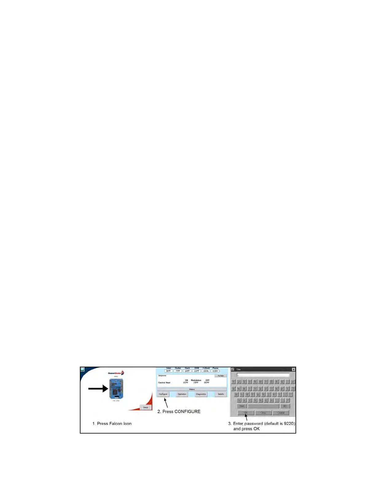
1. Log in at the Service level on the boiler hosting the lead lag Master (default password is 9220).