Section 2 — Installation
Part No. 750-363 2-23
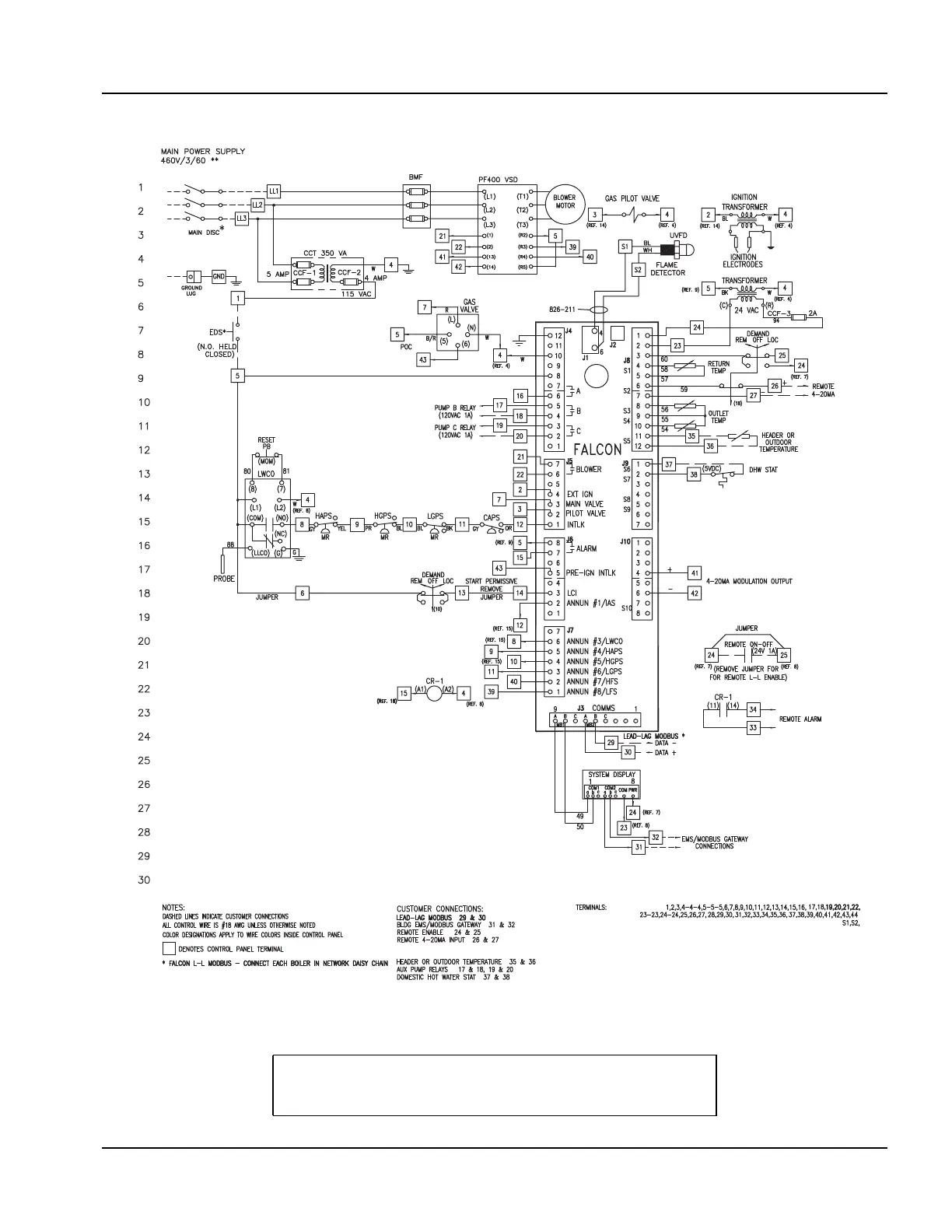
2.12 WIRING DIAGRAM
Figure 2-14 CFLC 6000 - 12000 Wiring Diagram, single fuel (typical)
Note: Wiring diagrams shown are examples only.
Installations may vary. For specific installations
consult the wiring diagram provided with the boiler.
208V, 230V, 575V 3 PHASE ALSO SUPPORTED