Appendix C Gas Valve
C-30
7. Tighten the scr ews on the metal strain relief.
The maximum tor que for each metal str ain relief scr ew
is 4.4 in-lb (0.5 Nm).
8. Assemble
-
9. R oute the “pig-tailed” wires from the valve connector
through the 1/2” conduit and to the nearest conduit body
(panel), and then screw the valve connector to the 1/2”
NOTE: It may be necessary to pull the wires at the nearest
conduit body to reduce any potential wire slack in the raceway
10. Assemble the cover and mounting screw to the valve con -
nector, and mount the valve connector to the valve coil as
shown below.
11. Tighten the mounting scr ew.
12. Follow NEC (NFPA 70) requirements for proper termination
at the nearest conduit body.
Failure to follow the exact instructions belo w ma y result
in a valve connector not
to valve.
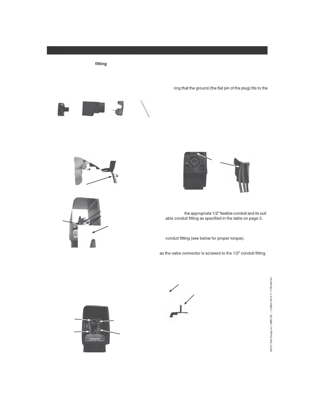
STEPS
1. After selecting the pr oper number of wires, push the mount -
ing screw completely out from the valve connector and
disassemble the remaining 4 parts as shown below:
2. Star ting from the 1/2” NPT end of the housing, push the
wires under the metal strain relief and through the housing
(see FIG. A below). The GREEN (ground) wire should be
placed into the far left groove when viewed as shown in
FIG. B. The “Neutral (-) ” should be placed into the groove
next to the GREEN (ground).
3. Continue to push the wir es through the housing until there
is at least an extra 3”- 6”available for connecting the wires
to the terminals on the T-Block (see FIG. A above).
4. Strip no mor e than 1/4” of insulation from each wire.
5. Wiring to the corr ect terminal is critical. The terminals are
labeled next to the terminal screws. Terminate each wire to
its proper terminal on the T-block. See FIG. C to determine
the proper terminals for the valve. NOTE: One neutral is
used to power both valves.
Mounting Screw
Terminal Block
(T-Block)
Cover
The maximum torque at the 1/2” NPT conduit
housing connection is 60 in-lb (6.75 Nm).
Fig. A
Strip the end of each
lead 1/4” maximum
push wires
pull 3”-6” of extra wire
Neutral -
Metal Strain
Relief
Ground
Fig. B
Fig. D
Ground
Fig. E
The maximum torque for mounting
screw is 8.8 in-lb (1.0 Nm).
Housing
The maximum tor que for the terminal scr ews is 4.4 in-lb
(0.5 Nm).
6. Pull the wires so that the T-Block is completely pulled into
the housing. As the T-Block gets pulled into the housing,
the T-Block and the wires must be properly guided into the
housing by:
A) Ensu
front of the housing as shown in FIG. D below,
AND
B) Ensu ring that the wires lay side-by-side beneath the metal
strain relief as shown in Fig. E below,
AND
C) Organizing the wires so that they terminate on the same
side of the connector under which they were routed. The
wires must NOT crisscross inside the housing to the op -
posite side from which they are terminated. Fig. C illustrates
how the wires terminate on the same side under which they
were routed.
Terminal #2
Hot (+) for valve #1
Terminal #3
Hot (+) for valve #2
Ground
Terminal #1
Neutral (-)
Fig. C
Hot +
Electrical DIN Connector assembly & wiring