Falcon Lead Lag Appendix E
E-10
NOTE: refer to specific boiler wiring diagram for proper terminal numbers.
Sensor Configuration (steam)
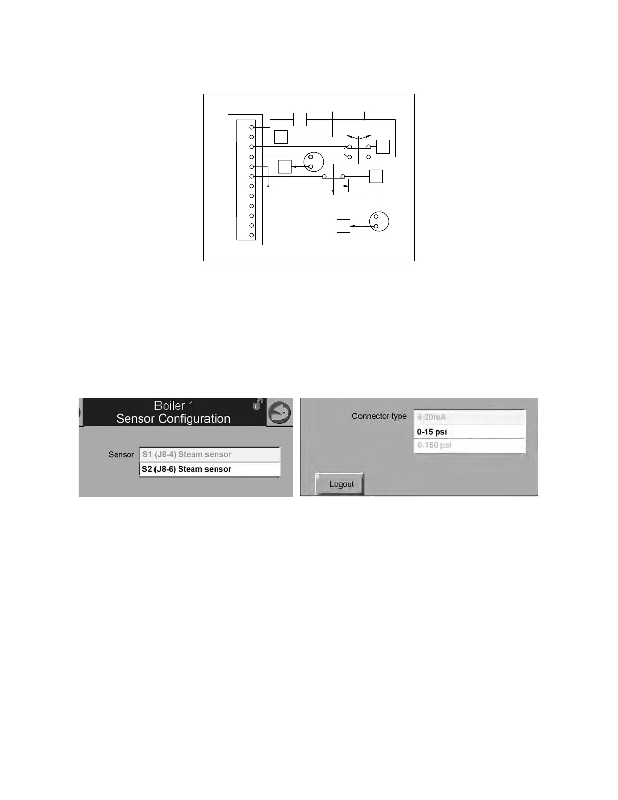
For steam systems the header pressure transmitter input needs to be configured at the Master host.
Go to CONFIGURE>Sensor Configuration and from the pull-down menu select S2 (J8-6). For
“Connector type” select 0-15 psi or 0-150 psi according to the design pressure of your system. Do
not use the 4-20mA selection. The remote 4-20mA input is unavailable on Falcon steam lead lag
systems.
6.3 - Outdoor Temperature Sensor (optional; hot water only)
The outdoor temperature sensor, if used, may be connected to control panel terminals 35 and 36
on any available boiler in the network (other than the boiler hosting the Master). Once configured,
the sensor will be recognized by the lead lag Master.
Sensor Configuration (hot water)
The Outdoor Reset, Warm Weather Shutdown, and Frost Protection routines all make use of the
outdoor temperature. To configure the outdoor temperature sensor, go to the boiler that has the
sensor connected (see 6.3 above for sensor connection).
1. Starting from the display home page, go to VIEW INDIVIDUAL>CONFIGURE>Sensor Configura-
tion.
2. Under Outdoor temperature source Select ‘S5 (J8-11) Sensor’.
Once configured, the sensor will be recognized by the lead lag Master over the Modbus network.
Figure 5 - Header press. transmitter (steam)
23
10
5
24
J8
25
DEMAND
REM
LOC
OFF
60
S1
S2
S3
S4
S5
XMTR
BK
BR
PRESS
-
+
BK
BR
-
+
26
27
59
(18)
28
28
58
+12VDC
FALCON
FALCON LEAD LAG MASTER ONLY:
L-L HEADER PRESSURE XMTR