Appendix E Falcon Lead Lag
E-9
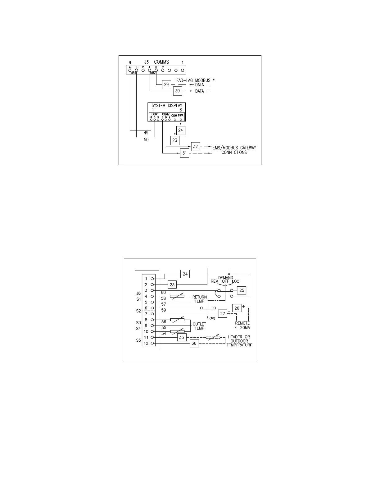
6.2 - Header Temperature Sensor (hot water systems)
Determine which boiler will be the lead lag Master host and connect the header temperature sensor
to this boiler at the appropriate control panel terminals.
Temperature sensor (hot water): Terminals 35 and 36 (Falcon terminals J8-11 and J8-12; sensor
input S5). See Figure 4a.
NOTE: refer to specific boiler wiring diagram for proper terminal numbers.
6.3 - Header Pressure Transmitter (steam systems)
Determine which boiler will be the lead lag Master host and connect the header pressure transmitter
to this boiler at the appropriate control panel terminals.
Pressure transmitter (steam) - 2-wire, 4-20mA: Terminals 26 and 28 (Falcon terminals J8-6 and
power supply VDC+; J8-7 is jumpered to VDC- see Figure 4b).
Figure 3 - Falcon communication wiring
Figure 4 - Header temp. sensor (hydronic)