Falcon Lead Lag Appendix E
E-4
2- SYSTEM REQUIREMENTS
Hydronic Systems
• 2-8 boilers equipped with Falcon hydronic controls. All Falcon controllers in a Lead/Lag
network must have compatible software versions.* To check the software version on a
particular Falcon controller, use the touchscreen display and go to Configure>System
Identification and Access.
When combining controllers with different software versions in a Falcon lead/lag net-
work, choose one with the most recent software revision as the Master Host (see Sec-
tion 4).
All boilers in a hydronic lead/lag system should be of a compatible type (condensing or
non-condensing).
• Modbus network connecting all Falcon boiler controllers in the system.
• System header temperature sensor (required for lead lag operation).
• An outdoor temperature sensor may be connected to an available Falcon sensor input for
outdoor reset control (optional).
• 833-05105 or 833-03577 display for each boiler.**
A Falcon lead lag kit 880-3670 is available from Cleaver-Brooks and includes a system header
temperature sensor with thermowell, outdoor air temperature sensor, and Falcon Program Module
for copying parameter settings from one Falcon to another.
* Software version 1987.2432 or later required.
** If 833-03577, software version 1.3.1 or later required (1.4.0 or later for Building EMS communication).
Steam Systems
• 2-8 boilers equipped with Falcon steam controls. All Falcon controllers in a Lead/Lag
network must have compatible software versions.* To check the software version on a
particular Falcon controller, use the touchscreen display and go to Configure>System
Identification and Access.
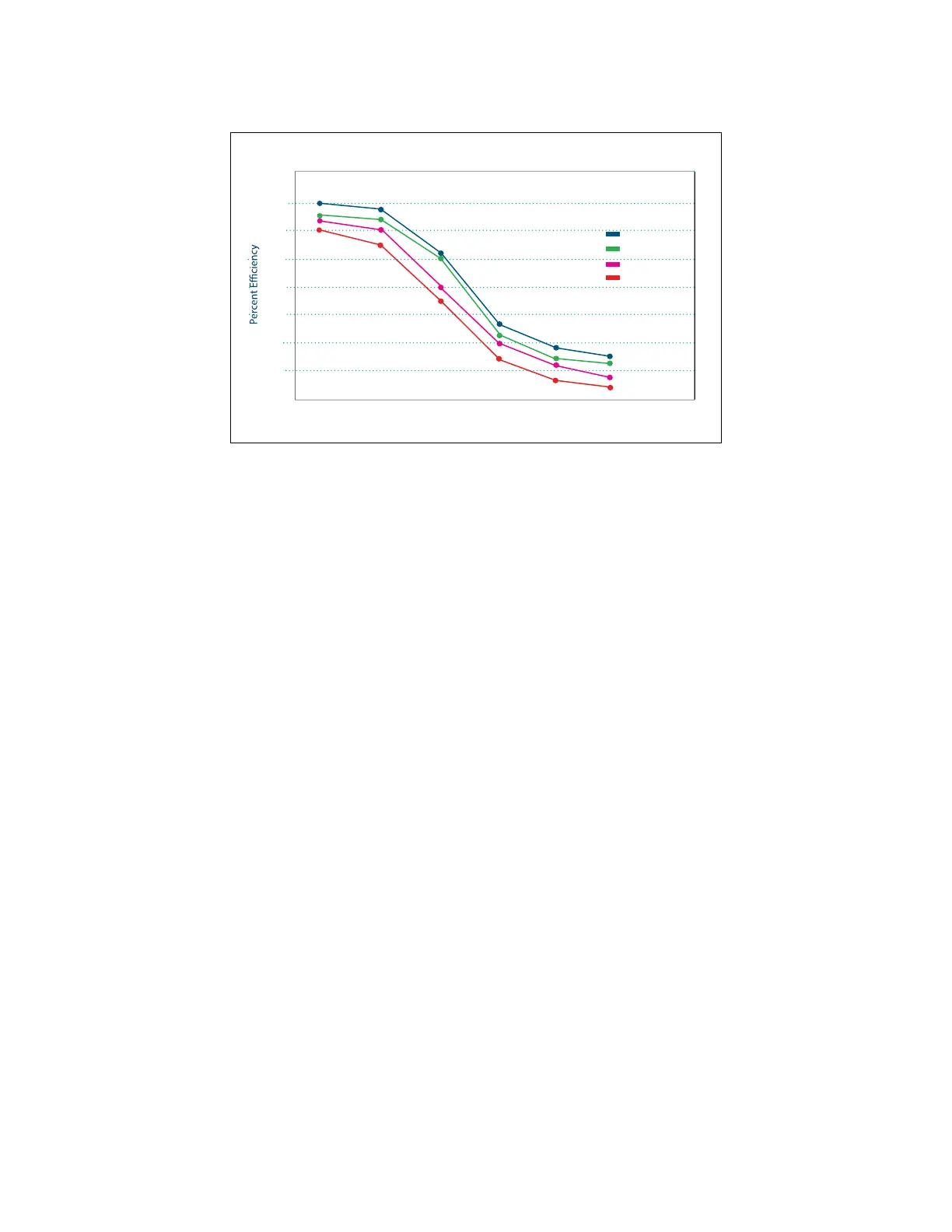
Figure 1 - CFC Efficiencies
101%
99%
97%
95%
93%
91%
89%
87%
85%
Return Water Temperature
68
° 86° 104° 122° 140° 158°
20
50
75
100
Single return eciency as a function of temperature and ring rate
Firing Rate Percentage