Appendix C Gas Valve
C-38
This test method is an alternative to bubble tightness testing
downstream of the MBC.
Preparation for leak testing:
1) Ensure that the appliance is not in operation.
2) This test requires:
• A manometer capable of r eading +/- 0.1”WC.
• A stop watch.
the valve test port.
3) The -
valve downstream of the MBC, if installed, must remain
open during this test.
4) The test also requires the ability to open and close safety
valve #1 and safety valve #2 independently using the volt -
age as indicated on the coil.
5) Externally leak test the valve and all piping connected to
the manometer connection. DUNGS recommends using
an all purpose liquid leak detector solution (Snoop™ or
a non-aggressive soapy water solution). The presence of
bubbles indicates a leak.
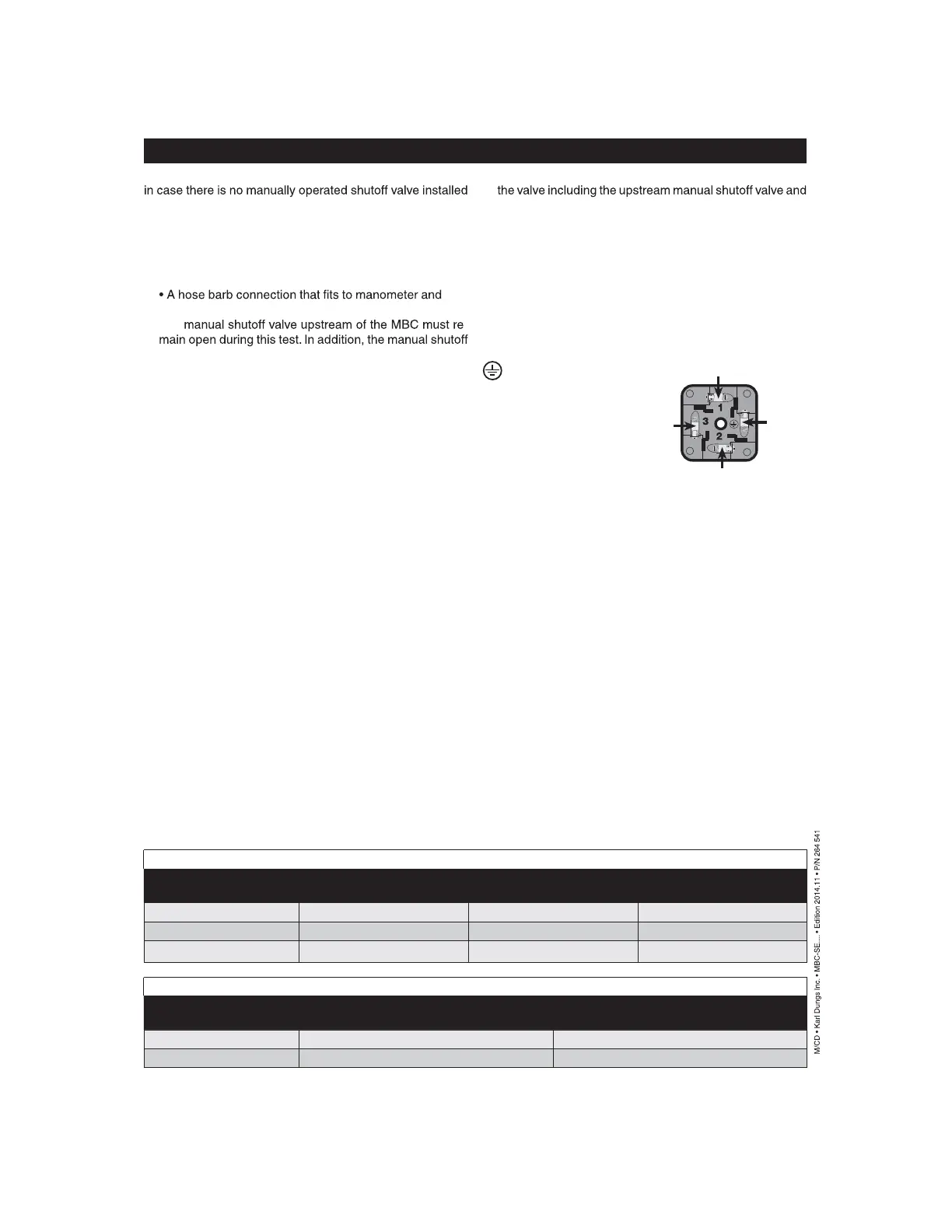
6) The DIN connec tor of the MBC Valve has three connections
that provide power to the coil along with a ground connec -
tion. Pin numbers indicated on DIN connector.
Pin # 2 = Line voltage Valve #1
Pin # 3 = Line voltage Valve #2
Pin # 1 = Neutral Valve #1 & 2
= Gr ound
Procedure for Testing Valve #1
1) Connect a manometer to P ort 2 on the side of the MBC
2) Determine the test time accor ding the valve size, as indi -
cated on table 1.
3) Ener gize valve 2 by powering terminal 3 with the voltage
indicated on the coil housing. Ensure that terminal #1 is
connected to Neutral and that the safety ground is also
connected to ground.
4) Mar k the pressure reading on the manometer, which should
be zero.
5) With a stopwatch ready, de-energize valve 2 and imme -
diately start the timer. Watch
the manometer for pressure
change.
6) As soon as the test time e xpires, determine the amount of
pressure rise. Reference table 2 for action to be taken.
Procedure for Testing Valve #2
1) Connect a manometer to P ort 2 on the side of the MBC
2) Determine the test time according the valve size, as indi -
cated on table 1.
3) Ener gize valve 1 by powering terminal 2 with the voltage
indicated on the coil housing. Ensure that terminal #1 is
connected to Neutral and that the safety ground is also
connected to ground.
4) Mar k the pressure reading on the manometer, which should
be equal to the inlet pressure to the valve.
5) With a stopwatch ready, de-energize valve 1 and imme -
diately start the timer. Watch the manometer for pressure
change.
6) As soon as the test time e xpires, determine the amount of
pressure change. Reference table 2 for action to be taken.
After completing the above tests:
1) R emove the manometer, and close Port 2.
2) Use soapy water to leak test all connections including Port
2 to ensure that there are no leaks.
Valve Leakage Decay Test
Leakage rates according to UL 429 and ANSI Z21.21
Test time (s) Allowable leakage (cc/hr) Maximum pressure drop
(in. W.C.)
MBC 1000 4.0 235.0 2.0
MBC 2500 5.0 305.0 2.0
MBC 4000 6.0 470.0 2.0
Analysis of test results
Pressure drop / rise
(in. W.C.)
Acceptable Test results
2.0 or less Yes Pass
More than 2.0 No Fail - Immediately replace valve
-L2 (AC) Neutral
- (DC)
Ground
L1 (AC) Hot
+ (DC)
Valve 1
L1 (AC) Hot
+ (DC)
Valve 2