Section 4 — Commissioning
Part No. 750-363 4-11
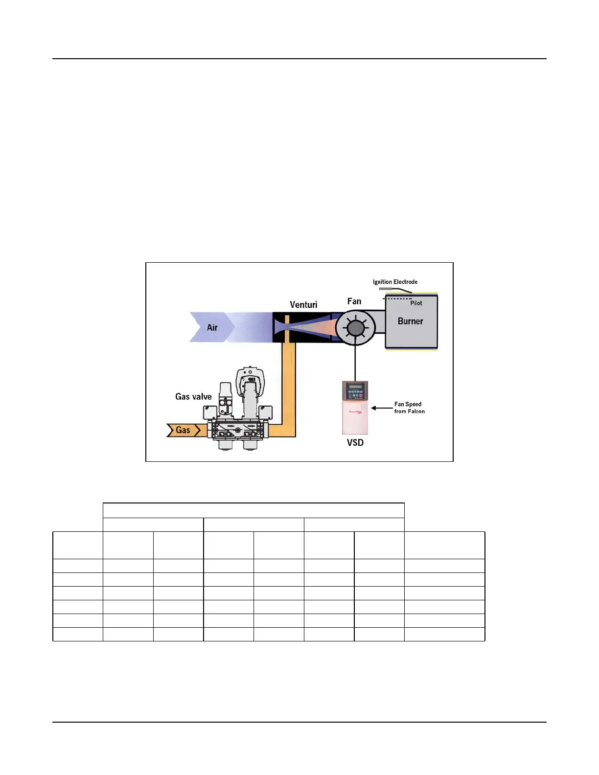
in pressure due to the venturi effect. The modulating controller of the valve actuator senses air pressure
change and accordingly brings about a change in the gas flow proportional to the air pressure. The gas
follows the airflow in a set ratio, so that fuel always matches the air as the burner firing rate increases or
decreases.
1. Check the gas delivery system to be sure it is properly piped and wired.
2. Review available gas supply pressure to ensure that it is compatible with the ClearFire’s gas train and
regulator. Refer to Table 4-1 for minimum required supply pressure and maximum allowable supply
pressure.
3. To bleed air from the supply pipe, open the manual gas shut off valve upstream of the burner gas train
and bleed air from the piping by loosening the union in the upstream piping.
4. The burner and its gas connection must be leak tested before placing the boiler into operation.
5. Gas Pressure Regulator - Using the adjusting screw on the main gas regulator, adjust the gas valve inlet
pressure to within the recommended levels in Table 4-1.
Table 4-1 CFLC gas pressure requirements
*Listed max. pressures are without the use of a step-down regulator. The CFLC can accommodate higher supply pressures with the addition of an upstream regulator.
*When an upstream regulator is installed, required minimum pressures will be higher due to the pressure drop across the regulator.
CFLC 4000-5000 >1/2 psig requires step-down regulator
>5 psig requires overpressure protection
CFLC 6000-12000 >2 psig requires step-down regulator
>7 psig requires overpressure protection
Figure 4-9 Premix Burner Technology - Full Modulation
Gas Supply Pressure (at gas regulator outlet)
Natural Gas 20ppm Natural Gas 9ppm Propane
Boiler
size
Min
(“WC)
Max*
(“WC)
Min
(“WC)
Max*
(“WC)
Min
(“WC)
Max
(“WC)
Gas pilot pressure
(“WC)
4000 9 14 10 14 9 14 3-5
5000 9 14 10 14 9 14 3-5
6000 35 56 35 56 31 56 3-5
8000 35 56 42 56 31 56 3-5
10000 38 56 38 56 35 56 3-5
12000 38 56 40 56 35 56 3-5