Section 4 — Commissioning
4-20 Part No. 750-363
Configurable Pump/Aux Relay Contacts
The Falcon Pump/Aux Relay outputs are configurable by means of six pre-configured Pump Control Blocks.
Each control block is configured for a specific application:
1. Central Heat Pump
2. Boiler Pump (for primary/secondary pumping)
3. DHW pump
4. System Pump
5. “Aux 1 Pump” - used for a boiler isolation valve
6. “Aux 2 Pump” - used for a boiler Start Permissive Interlock
Each pump control block has seven parameters (for details see Falcon Lead Lag appendix):
Pump Options (2 parameter blocks) - determine pump on/off conditions
Start Delay - if burner is just starting up, timer will delay pump turning on
Overrun Time - keeps the pump running for a short time after the input turns off or demand is satisfied
Output Connection - selects Pump A, B, or C (refer to WD, Figure 2-10)
Cycle Count - one cycle counter for each pump output; can be reset if a pump is replaced
Pump Control - selects Auto or Manual control
A Pump Exercise routine helps to prevent pumps from freezing up due to long periods of inactivity.
Configurable parameters are Pump Exercise Interval (days) and Pump Exercise Time (minutes). Any pump
that remains off for the Pump Exercise Interval will be turned on for the duration given by Pump Exercise
Time.
The relays may be configured for various other functions, including freeze protection, isolation valves,
damper interlocks, operating status, etc.
Annunciator
The Annunciator monitors the Falcon control circuit to provide fault and status messages, and also provides
first out annunciation for interlock lockouts. Eight inputs are available in addition to the Interlock, Load
Control, and Pre-Ignition Interlock inputs, totaling 11 monitored points. Annunciator points can be accessed
via the Falcon display Operation screen.
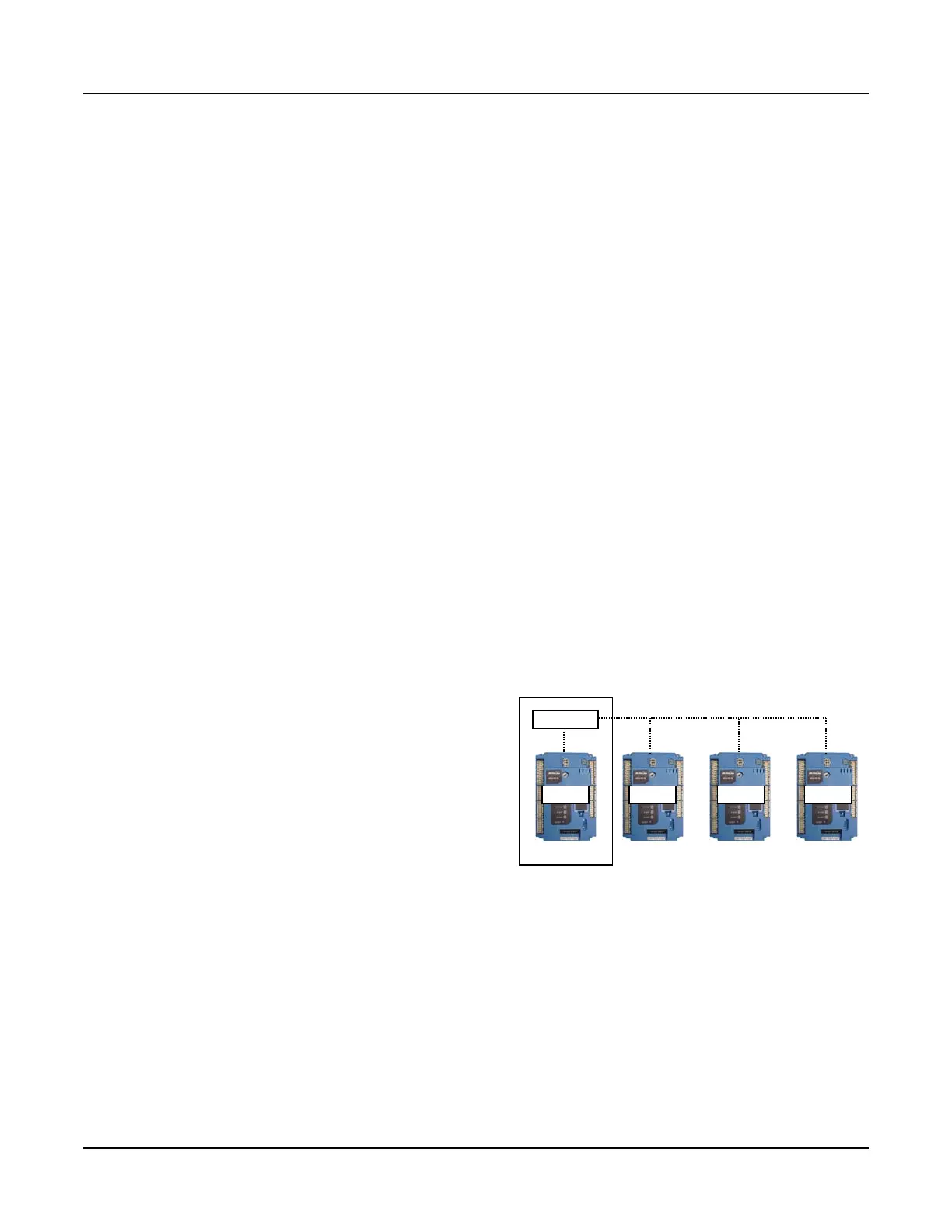
Lead/Lag Control (up to eight boilers)
Multiple Falcon units can be connected in a lead/lag
system. Controllers in a lead/lag configuration
communicate over the Falcon’s MB2 Modbus network.
One Falcon in the lead/lag network hosts the Lead Lag
Master function, which coordinates the activities of the
Slave units (individual Falcons, including the one hosting
the Master) via Modbus. The Master uses its host
controller’s header sensor to receive control input
information and to maintain the optimum setpoint. An
outdoor temperature sensor can also be connected for
Lead Lag outdoor reset control.
Boiler sequencing, on/off staging, and firing rate allocation are user-configurable. The Falcon’s default lead
lag parameter settings have been optimized specifically for ClearFire-C condensing boiler operation.
Refer to the Falcon Lead/Lag appendix in this manual for additional information.
Modbus Communication
For remote enable / remote setpoint (see above) and for remote monitoring through a building EMS, the
Falcon uses the Modbus communication protocol. For more information on Modbus setup and
implementation, see the Falcon Lead Lag appendix in this manual.
SLAVE SLAVE SLAVE SLAVE
MASTER
Figure 4-13 Falcon Lead/Lag