Appendix C Gas Valve
C-32
MBC...SE
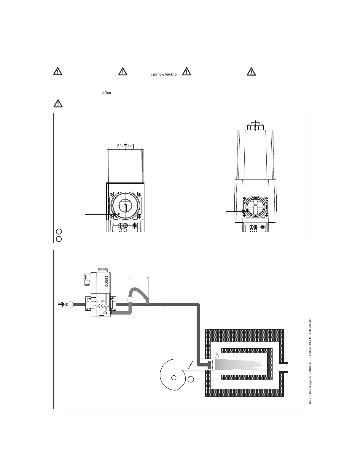
Recommended Installation of Impulse lines when used (optional)
M
1
2
20
16
12
8
4
p
Br
min. 5 x
Diameter
Diameter
External Impulse line (option)
Assembly Instructions
Impulse line p
BR
must cor -
respond to ≥ DN 4 (1/8”), PN
1 and they must be made of steel.
Other materials for Impulse lines
are only per mitted after a cer
-
tion with the burner / boiler.
Close internal Impulse line
with grub scr ew. See Fig. 1
Route Impulse line so that no
condensate
the MBC...SE. See Fig. 2
1 2
1
2
MBC 1000/2500
Fig. 1
MBC 4000
Secure Impulse line to prevent
them from being ripped out and
deformed.
Keep Impulse line short!
Test Impulse line for external
leakage. Use leakage spray
only if necessary.
Te st pr e s s ur e :
p
max.
= 40” W.C.
Close this port
with grub screw
if using external
feedback
Close this port
with grub screw
if using external
feedback
1
2
external feedback
breathing port