Falcon Lead Lag Appendix E
E-66
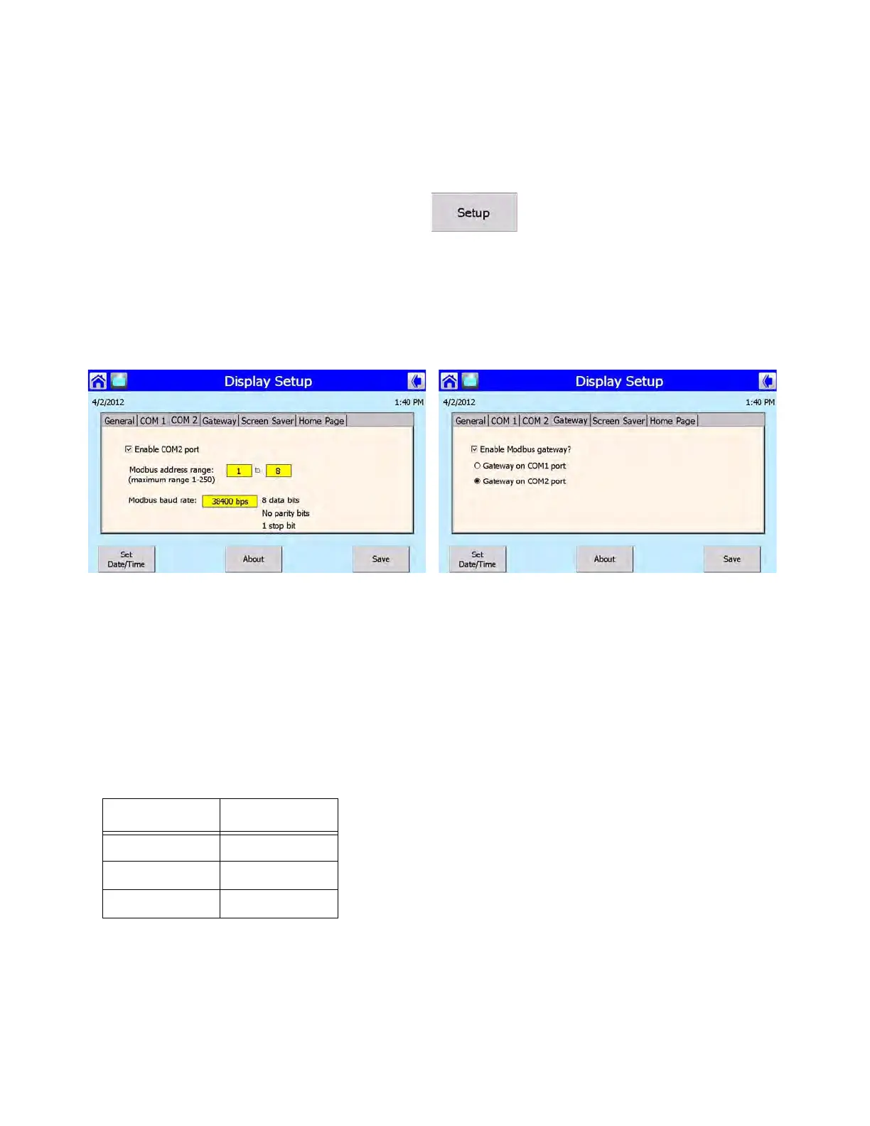
ENABLING MODBUS COMMUNICATIONS
To establish communications with a building EMS, each Falcon display in the lead lag network must
have its COM 2 Modbus port enabled. Use the following steps to enable:
1. On the display Home page press <SETUP>.
2. Go to <DISPLAY SETUP>.
3. Go to the COM 2 tab. The Modbus address range can be set here (maximum 1-250). The Mod-
bus baud rate can also be changed here if necessary (selectable between 38400, 19200, or
9600).
4. Go to the Gateway tab. Make sure ‘Enable Modbus Gateway?’ is checked. Select ‘Gateway on
COM2 port’.
NOTE: The Modbus Gateway must be enabled at each boiler in the lead lag network (not just the
Master host) for individual boiler status monitoring.
INTERFACE
Physical Layer
The Falcon Modbus port is a 3-pin connector that interfaces to RS-485 signals as indicated in Table 1.
The serial transmission mode on the Modbus network is the RTU mode. Message format is shown in
Table 2.
Table 4: RS-485 signals
Signal Terminal
Data + (a) 1
Data - (b) 2
Common (c) 3