Appendix C Gas Valve
C-39
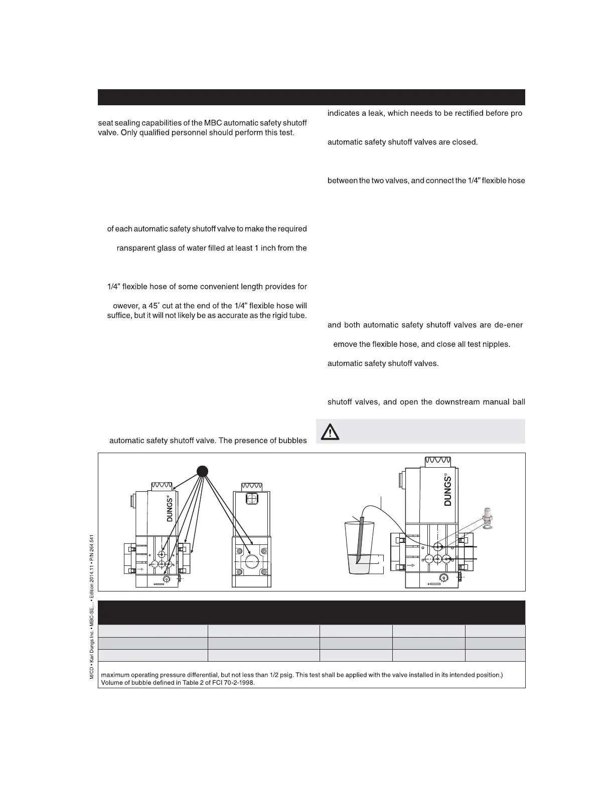
Valve Leakage Bubble Test (Altern. method)
This leak test procedure tests the external sealing and valve
It is required that this test be done on the initial system startup,
and then repeated at least annually. Possibly more often de -
pending on the application, environmental parameters, and
the requirements of the authority having jurisdiction.
Setup
This test requires the following:
A) Test nipples installed in the downstream pressure tap port
1/4” hose connection in step 4.
B) A t
bottom.
C) A proper leak test tube. An aluminum or copper 1/4” rigid
tube with a 45˚ cut at the end that is then connected to a
a more accurate leakage measurement.
H
D) For detecting external leakages, an all purpose liquid leak
detector solution or a soapy water solution is required.
Leak Test Procedure
Use the illustration below as a reference.
1. With the upstream ball valve open, the downstream ball
valve closed and both valves energized, apply an all pur -
pose liquid leak detector solution to the “External Leak -
age Test Areas” indicated in the illustration below, to any
accessories mounted to the safety valve, and to all gas
piping and gas components downstream the equipment
isolation valve, and the inlet and outlet gas piping of the
-
ceeding.
2. Then, de-energize the burner system and verify that both
3. C lose the upstream and downstream manual ball valve.
4. Using a screwdriver, slowly open the V1 test nipple (port 2)
by turning it counter clockwise to depressurize the volume
to the test nipple.
5. S lowly open the upstream manual ball valve, and then pro -
vide for some time to allow potential leakage to charge the
test chamber before measuring the valve seat leakage.
6. Immerse the 1/4 in. tube vertically 1/2 in. (12.7 mm) below
the water surface. If bubbles emerge from the ¼” tube and
after the leakage rate has stabilized, count the number of
bubbles appearing during a 10 second period. (See chart
below for allowable leakage rates.)
7. R epeat the same procedure for valve V2 (port 3).
(Energize terminal 2 on the DIN connector to open valve 1)
After completing the above tests proceed as follows:
8. Verify that the downstream manual ball valve is closed,
-
gized.
9. R
10. With the upstream manual ball valve open, energize both
11. Us e soapy water to leak test all test nipples to ensure that
there are no leaks.
12. If no leakage is detected, de-energize all automatic safety
valve.
Type Allowable Valve Seat # of Bubbles in 10 s
Leakage* up to 7 PSI inlet Air Natural Gas LP
MBC 1000 235 cc/hr 5 6 4
MBC 2500 305 cc/hr 7 8 6
MBC 4000 470 cc/hr 10 11 9
*Based on air and test conditions per UL 429 Section 29. (Air or inert gas at a pressure of 1/4 psig and also at a pressure of one and one-half times
If leakage values are exceeded, replace valve
immediately.
20
16
12
8
4
p
Br
Leak Test Here
20
16
12
8
4
p
Br
1/2”
1”
1/4 “ Rigid Tube
1/4 “ Flex Hose
G 1/8” Test Nipple
# D219 008
Port 2
Leak Test for V1
Port 3
Leak Test for V2