Appendix E Falcon Lead Lag
E-65
MODBUS
Building Energy Management System (EMS) interface
The following is used as a reference in this document:
MODBUS Application Protocol Specification V1.1a, June 4,
2004, http://www.Modbus-IDA.org.
This appendix describes the interface to the CB Falcon boiler controller on either the MB1 or MB2
Modbus port and the Falcon display COM 2 port. These ports are RS-485 connections that use the
Modbus communication protocol to allow configuration and status data to be read from and written
to the Falcon.
The CB Falcon functions as a Modbus Slave on this interface. It responds to a single Modbus address
to service the requests of the Modbus Master on the RS-485 network.
Definitions
The following definitions apply in this appendix:
Modbus—Application layer communication protocol standard adopted by the Modbus-IDA trade association.
Recognized as an industry standard protocol for RS-485 serial communication.
RTU—Remote Terminal Unit serial transmission mode. Mode used to encode data for Modbus where each 8-
bit byte is sent as two 4-bit hexadecimal characters.
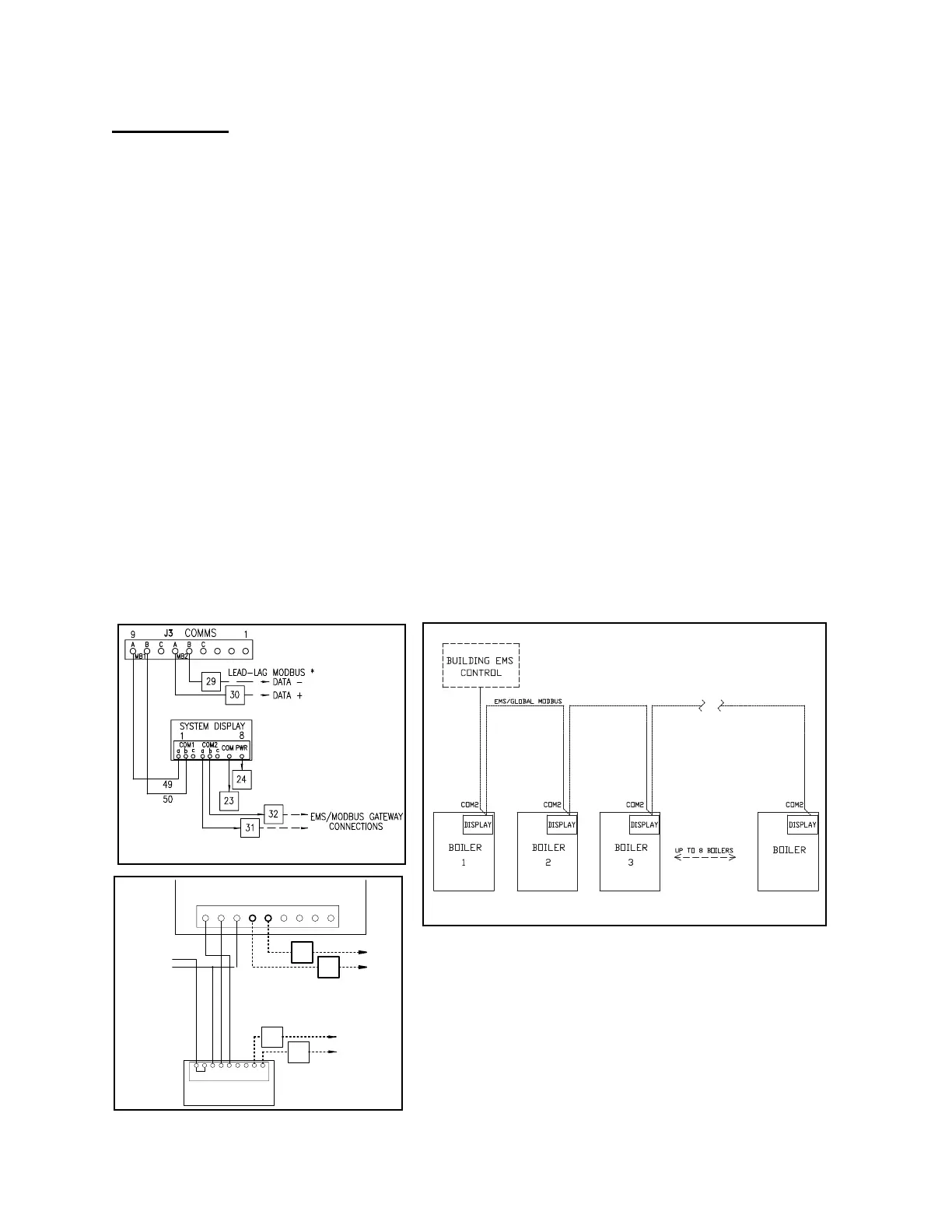
WIRING
Shown below are wiring connections at each boiler and network connections for EMS communica-
tion.
12 VDC
+
-
SYSTEM DISPLAY
1
9
JUMPER
COM1 COM2
b a a b
RED BLK WH
DATA+
DATA-
DATA+
DATA-
39
40
41
42
EMS/GLOBAL MODBUS
CONNECTIONS
LEAD/LAG
MODBUS
9
1
J3 COMMS
MB1
MB2
A B C A B C