Falcon Lead Lag Appendix E
E-8
6- SYSTEM SETUP
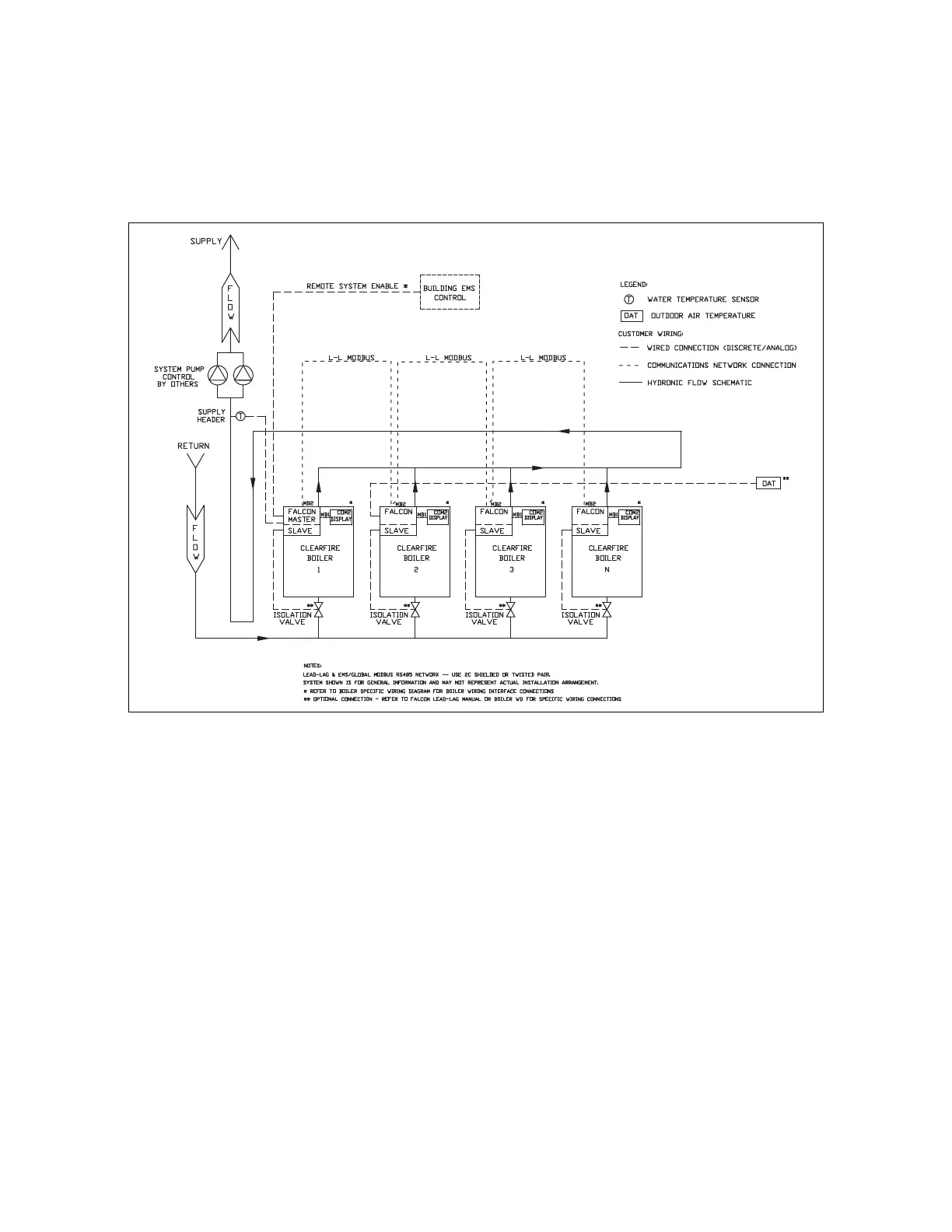
<Color>Figure 2 shows a basic Falcon lead lag system consisting of a 4-boiler network with remote
enable and outdoor air temperature reset.
6.1 - Lead Lag Modbus Network
Falcon controllers should be connected in a ‘daisy-chain’ manner (see <Color>Figure 2) over the
MB2 bus using 18 AWG 2-conductor shielded or twisted pair cable. Connections are made at
control panel terminals 39 and 40 (see <Color>Figure 3) or can be directly landed on the Falcon
controller’s MB2 A and B terminals.
Figure 2 - Four Boiler Lead Lag System