Appendix C Gas Valve
C-35
B
4. C
cover, Fig. 3.
5. Disconnect grounding and
PCB connectors, Fig. 4.
6. R eplace solenoid, Fig. 5
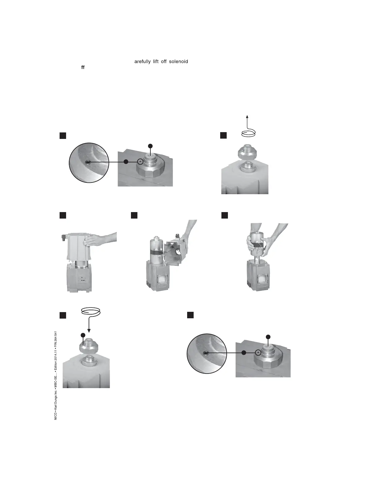
MBC-4000
1. Shut o
gas s upply and
disconnect power s up -
ply!
2. U ndo locking screw A, Fig. 1.
3. R emove cover B, Fig. 2.
1
2
3 4 5
6
B
A
B
A
7
Note:
Coil V1 wire connection
black/white
Coil V2 wire connection
red/blue
Replacement s olenoid is
complete assembled.
7. Make electrical connec -
tions. Assemble in reverse
order.
8. R eattach cover B, tighten
securely by hand only, Fig. 6.
9. T ighten lock screw A as
far as the stop, Fig. 7.
 Loading...