ID-DCU-MARINE-2.2.2, ©ComAp – June 2015 - 120 -
ID-DCU-MARINE-2.2.2.pdf
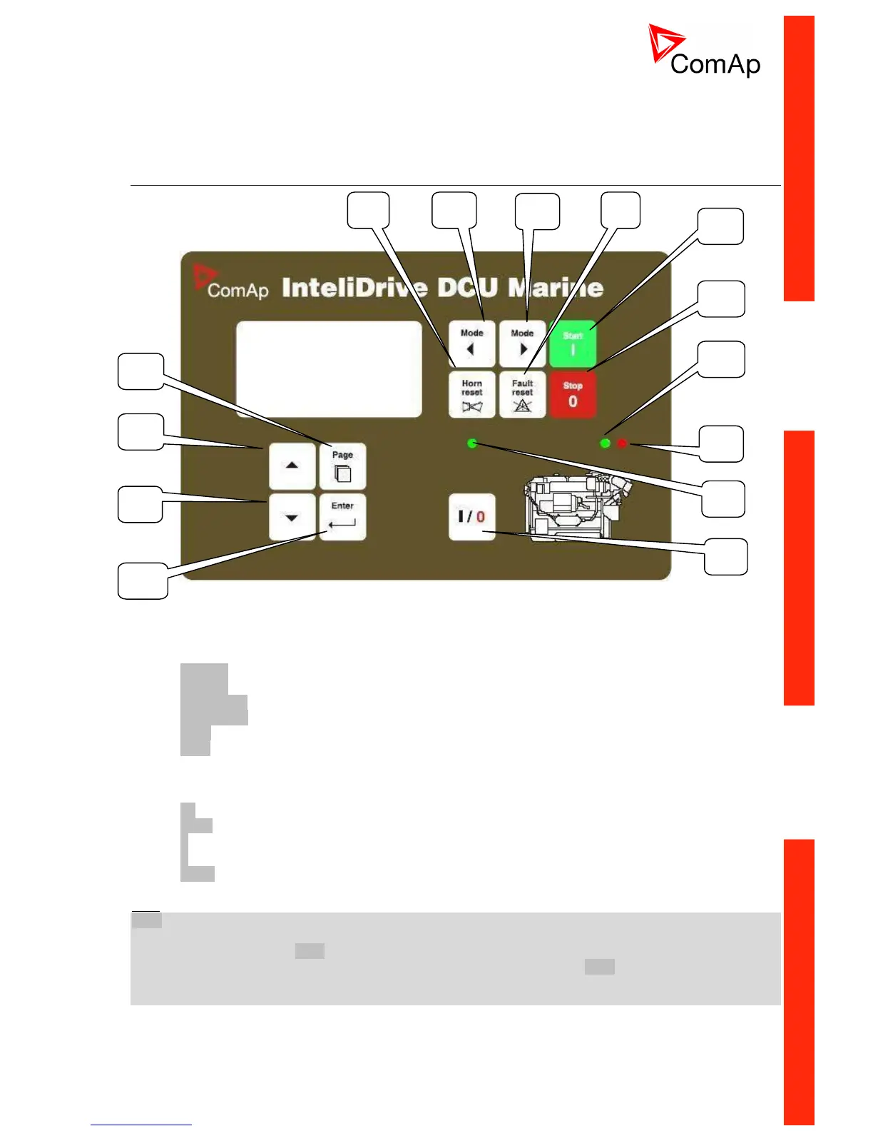
Operator Interface
Pushbuttons and LEDs
Pushbuttons and LED’s:
1. Mode-> Cycle forward through engine operation modes OFF -> AUX / EME / HRB / PRP.
2. <-Mode Cycle backward through engine operation modes OFF <- AUX / EME / HRB / PRP.
3. Horn reset Deactivates the HORN.
4. Fault reset Acknowledges faults and alarms.
5. Start Starts the engine in AUX, EME, HRB, PRP mode.
6. Stop Stops the engine in AUX, EME, HRB, PRP mode (hold time =1 sec).
7. GREEN = Engine OK.
8. RED = Engine fail.
9. GREEN = On/Off output is active.
10. I/0 button for Close load or Clutch Binary output control.
11. Page Cycles through the display screens MEASUREMENT->ADJUSTEMENT->HISTORY.
12. Select the set point, select the screen or increase set point value.
13. Select the set point, select the screen or decrease set point value.
14. Enter Confirm set point value.
Hint:
Stop button hold time is 1 sec. to avoid unwanted engine stop.
The 2
nd
(1 sec) push of the Stop button cancels the ‘cooling state’ of the engine and stops the engine
immediately. To avoid the cancel of the ‘cooling state’ by the 2
nd
push of the Stop button, use LBI card of the
DriveConfig tool and make the association of Access Lock to the Cooling logical binary output of the
‘Source’ column. It causes locking of the front panel buttons during the Cooling state.

 Loading...


