ID-DCU-MARINE-2.2.2, ©ComAp – June 2015 - 40 -
ID-DCU-MARINE-2.2.2.pdf
Getting started
How to install
Hint:
All components shall be used within marked electrical ratings – see chapter Technical data.
General
To ensure proper function:
Use grounding terminals. The InteliDrive DCU Marine power feeding input is galvanically isolated from
controller body, use the grounding terminal for proper grounding.
Wiring for binary inputs and analog inputs must not be lead parallel with high voltage/current cables.
Analog and binary inputs should be provided with shielded cables, especially when length >3m.
Power supply
Use min. power supply cable of 1.5 mm
2
to ensure proper function.
Maximum continuous DC power supply voltage is 36VDC. Maximum allowable power supply voltage is
39VDC – see chapter Technical data.
For redundancy power supply use ID-RPU module – see chapter Recommended wiring.
Hint:
The InteliDrive DCU Marine controller should be grounded properly in order to protect against atmospheric
discharges!
Install separate conductors for signal and power inputs. Allow for conductor voltage drop when determining
conductor size. All power supplies must have common ground.
When there is a potential risk of the controller being subjected to conditions outside its capabilities - an
outside protection device should be used.
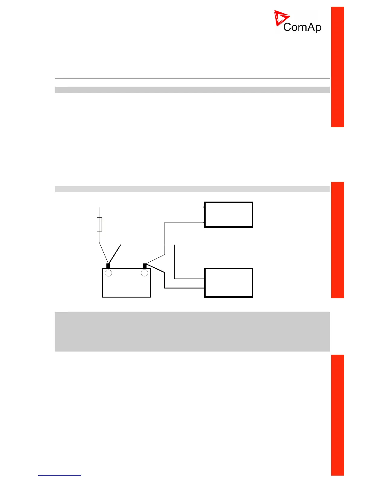
Power supply fusing
External fuse rated max. 2.5A shall be used to limit current from the power supply to the controller and
modules. Controller and I/O modules should never be connected directly to the starting battery.
Fuse value and type depends on number of connected devices and wire length.
Recommended fuse (not fast) type - due to internal capacitors charging during power up.
Binary output protections
Do not connect binary outputs directly to DC relays without protection diodes. Use protection diodes even if
the relays are not connected directly to controller outputs. Use a fast recovery 3A / 50V diodes.

 Loading...


