ID-DCU-MARINE-2.2.2, ©ComAp – June 2015 - 13 -
ID-DCU-MARINE-2.2.2.pdf
Extension modules: EMS, IS-AIN8(TC), IS-BIN16/8, IGS-PTM, IGL-RA15
Intercontroller: I-RD-CAN-ID-DCU-MARINE, I-LB+, IG-IB, IB-NT,
others ID-DCU MARINE
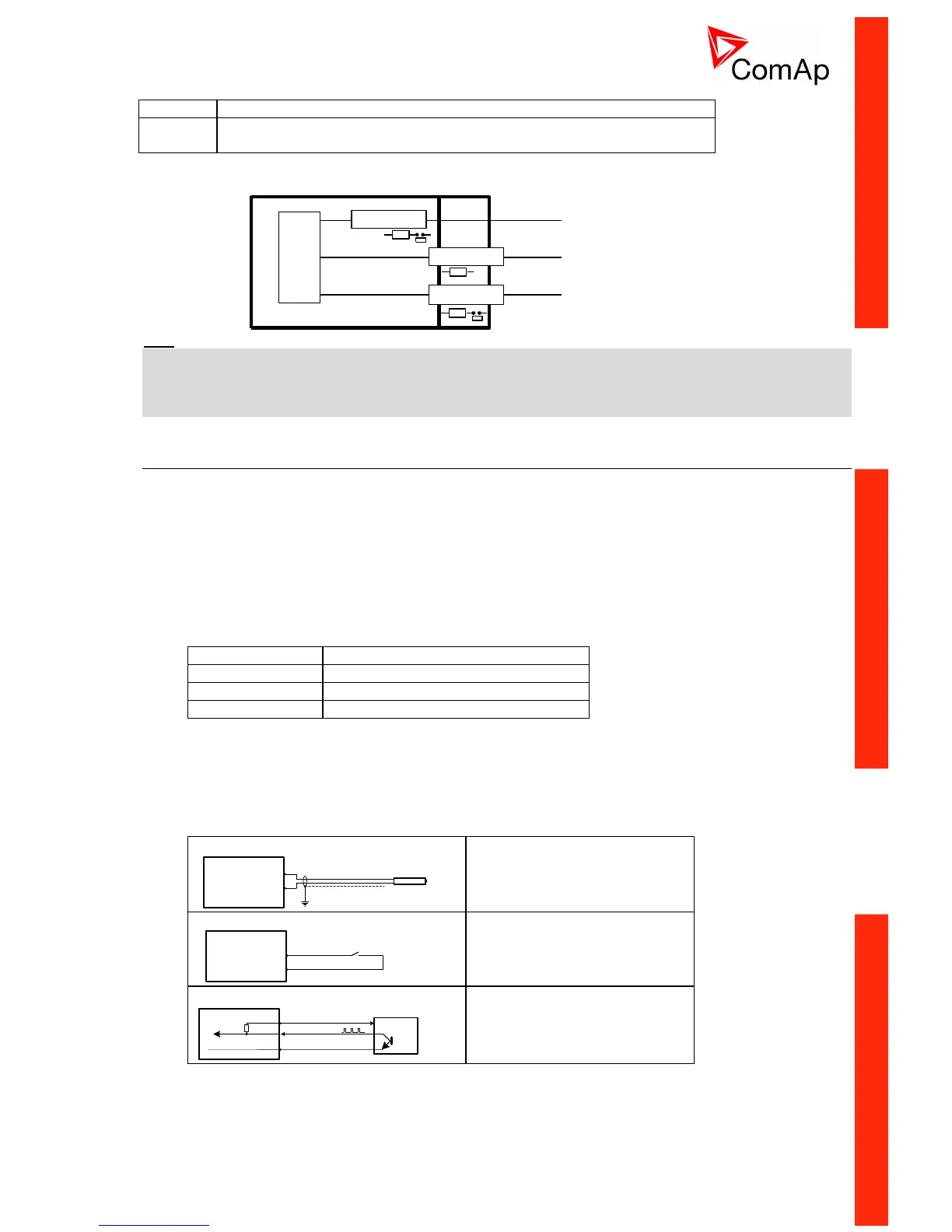
ID-DCU ID-COM
INTERFACE
INTERFACE
INTERFACE
CAN1
J1939
J1587
CAN2
PROCESSOR
TTL
TTL
TTL
120 ohms
120 ohms
Hint:
Put jumper to connect the internal 120 terminating resistor for CAN2 interface.
ID-COM module is not required when inter-controller CAN2 and J1587 lines are not used. In this case
connect Extension modules CAN1 directly to Extension modules port ID-COM on ID-DCU MARINE (9-pin
connector: 5=H, 9=L).
ID-SCM Speed control module
ID-SCM module is interface module for InteliDrive controller application. Module is mounted directly to ID-
DCU MARINE controller case. Module power supply: 8 to 36VDC.
Inputs
RPM1, RPM2: Two inputs for frequency (e.g. flow) measuring. Expected sensor is magnetic pickup – with
maximal frequency range up to 8 kHz. The output values SCM Freq1, SCM Freq2 calculation use setpoints
SCM unit: FreqRate1 and FreqRate2 - see below.
Closed jumper divides input frequency by 16 - recommended for higher frequency (>1000Hz) measuring.
Jumper position does not influence output value range.
RPM input nominal frequency range
IMP1, IMP2: Two impulse inputs for integral (e.g. consumption) measuring. It is expected NPN – open
collector (active) impulse sensor with maximal frequency range up to 60 Hz. Minimal pulse duration is 1ms.
The output values SCM Imp1, SCM Imp2 calculation use setpoints SCM unit: TransferRate1 and
TransferRate2 - see below.
ID-SCM inputs wiring example
RPM IN
RPM GND
Magnetic pickup
RPM1, RPM2
Magnetic pickup wiring to
RPM1 and RPM2 inputs.
PWR
IN
GND
Contact
IMP1, IMP2
Contact sensor wiring to
IMP1 and IMP2 inputs.
Active NPN
sensor
+24VDC
GND
IMP1, IMP2
PWR
IN
GND
Active NPN sensor wiring to
IMP1 and IMP2 inputs.

 Loading...


