ID-DCU-MARINE-2.2.2, ©ComAp – June 2015 - 157 -
ID-DCU-MARINE-2.2.2.pdf
Appendix
Recommended wiring according DNV rules
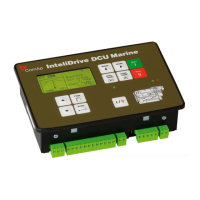
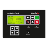
There is recommended wiring diagram of InteliDrive DCU Marine controller + ID-RPU module following latest
DNV requirements for mutual independency of control, alarm and safety systems. InteliDrive DCU Marine
provides features of control and alarm system, ID-RPU provides features of safety system.
Hint:
Fuses must be dimensioned in descending order in direction from batteries to devices.
Hint:
It is required to use two independent actuators for engine stopping
1. Actuator controlled by ID-RPU / STOP SOL output
2. Actuator controlled by ID-DCU / BOx output (configured to Stop Solenoid function)
Hint:
Emergency stop button contacts type NC (Normally Closed) can be directly incorporated into circuit
controlling ID-RPU / EM. STOP input. It is also acceptable to use relay NC contacts in the circuit connected
to ID-RPU / EM. STOP input (relay coil is controlled by emergency stop circuit) in case of NO (Normally
Opened) emergency stop circuit type, if it is required by application.

 Loading...


