ID-DCU-MARINE-2.2.2, ©ComAp – June 2015 - 8 -
ID-DCU-MARINE-2.2.2.pdf
Note:
ComAp believes that all information provided herein is correct and reliable and reserves the right to update
at any time. ComAp does not assume any responsibility for its use unless otherwise expressly undertaken.
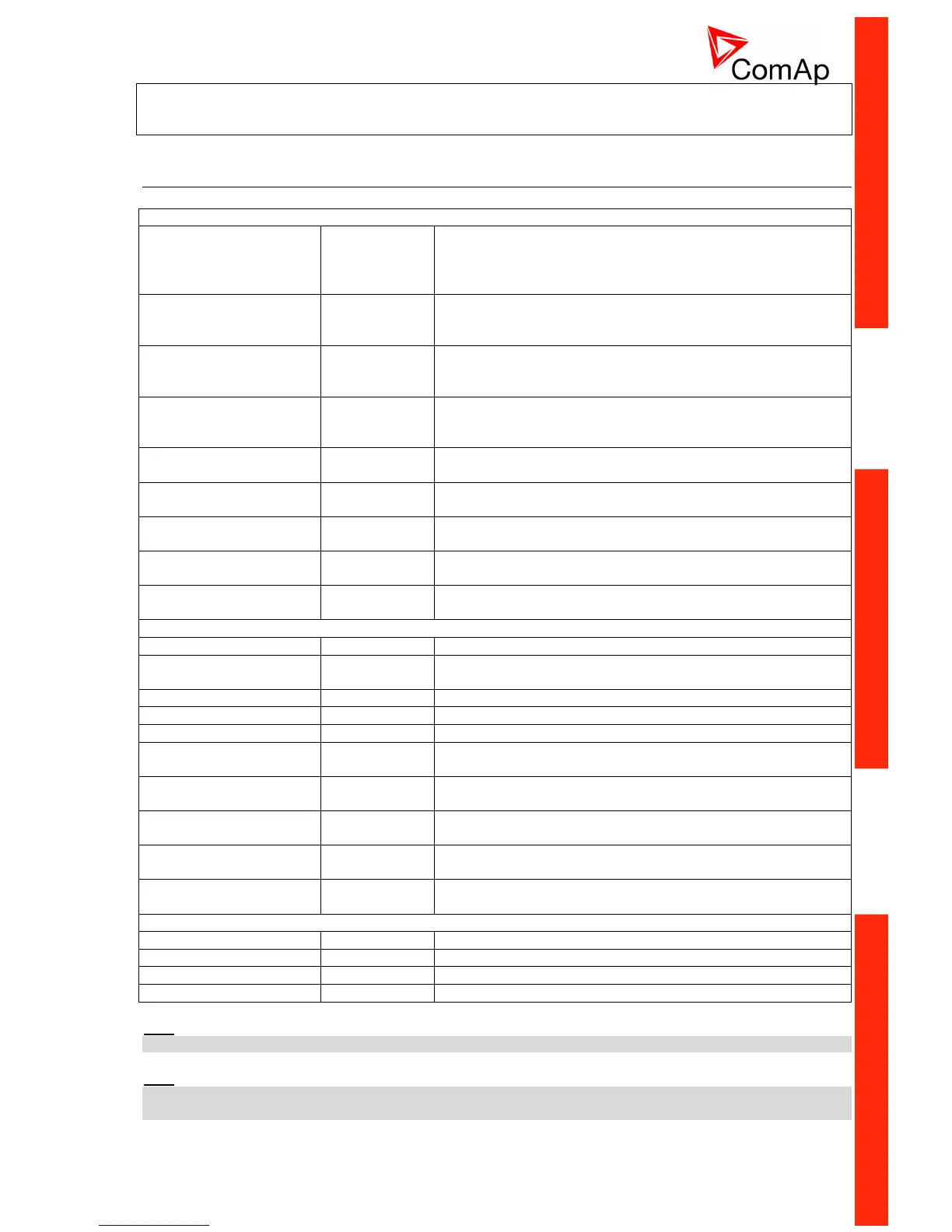
Physical component and interface Descriptions
InteliDrive central unit:
14 BIN, 14BOUT, 8 AIN,
1xRS232, 1xCAN1 (full), 1xCAN2 (TTL), 1x Sync.Data line
(TTL)
InteliDrive Redundancy Protection Unit with 5 SD and one
Emergency stop input one Wrn, Sd Fuel solenoid and one
Stop solenoid output.
Controller interface with two RPM inputs, two impulse inputs,
two analog outputs and one Speed governor (V, mA or pwm)
output.
InteliDrive Communication interface for inter-controller or
Remote display CAN2 line and for Redundancy synchronous
J1708/1587 data line.
16 relays with free NO/NC contacts 24VDC for binary outputs
separation
8 relays with free NO/NC contacts 24VDC for binary outputs
separation
InteliDrive Remote display (Slave panel), CAN or RS232
interface
InteliVision 8
InteliVision 8 Marine
InteliVision 5 CAN
InteliVision 5 CAN Backlit
Engine Electronic control unit
Configurable for
VDO, PT100, PT1000, Thermocouples, mA, Volts
Configurable for Thermocouples
Configurable for VDO, PT100, PT1000, mA, Volts
Configurable for Thermocouples
16 Binary inputs, 8 Binary outputs
8 (16) Binary inputs, 8 (0) Binary outputs, 2 Analog outputs
8 BIN, 8 BOUT, 4 AIN, 1 AOUT
8 Analog outputs selectable to 10VDC, 20 mA, pwm (2,4kHz)
External LED
indication panel
Configurable 15 LED and Horn signal.
Cellular/Ethernet interface
ECU communication interface
Hint:
IG-IOM extension unit is not compatible with ID-DCU MARINE controller.
Hint:
Inteli IO8/8 module is not fully supported in ID-DCU Marine 2.2, the module can be used with default
input/output configuration only, see corresponding chapter in this document.

 Loading...


