ID-DCU-MARINE-2.2.2, ©ComAp – June 2015 - 57 -
ID-DCU-MARINE-2.2.2.pdf
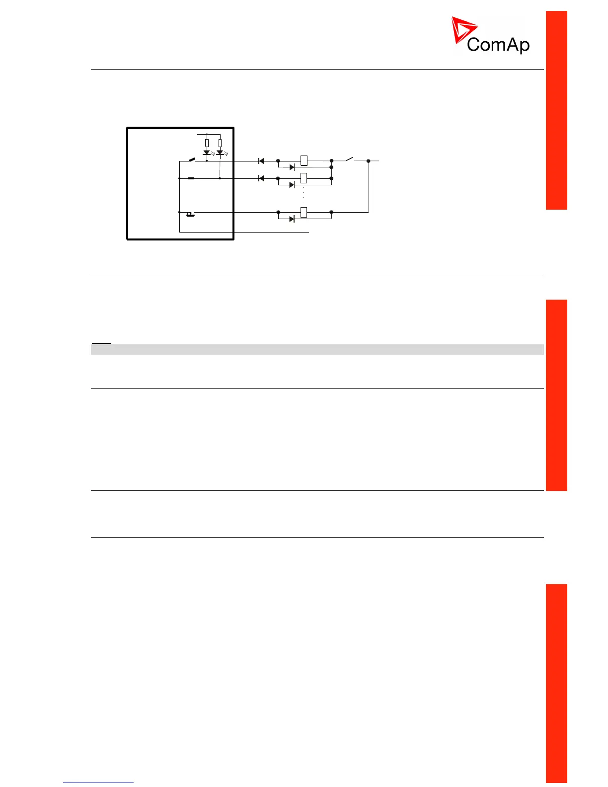
Binary output separation
In some special cases e.g. when Relays plus terminal is disconnected via EMERGENCY STOP contact, the
binary outputs must be separated using diodes to avoid false Binary output LED indication.
In the Example below when EMERGENCY STOP contact is opened, the BO3 LED should light (without
separating diode SD3) even if the BO3 output is opened.
IS-AIN8(TC), IS-BIN8/16 address setting
Press Address button during IS-AIN8(TC) power supply on to switch to addressing mode.
Then repeatedly press or keep pressed address button to adjust required address according to ID-DCU
MARINE configuration.
After setting requested address, release the buttons and wait until the digits blink – it indicates write the
changed address to EEPROM memory.
Hint:
CAN address 0 disables corresponding CAN message (Group data are not send).
Inteli IO8/8 address setting
Configuration as Inteli IO8/8 - CAN address for binary inputs is determined by DIP switch A, CAN
address for binary output and analog outputs is determined by DIP switch B.
Configuration as Inteli IO16/0 - CAN address for binary inputs is determined by DIP switch A, first
group of 8 input has address A, second group of 8 inputs has address A+1. CAN address of analog
outputs is set by DIP switch B.
In case of setting the CAN address to zero - the appropriate group of signals is deactivated.
Inteli AIN8(TC) address setting
DIP switch determinates CAN address for analog inputs.
IS-AIN8(TC), IS-BIN8/16 SW version check
Let suppose IS-AIN8(TC) of SW version 1.4. Shortly press address button. Following sequence appears on
the display: number “1”, one second pause, number “4”, two second pause, number “1”, one second pause,
number “4”, two second pause and finally IS-AIN8(TC) actual address.

 Loading...


