ID-DCU-MARINE-2.2.2, ©ComAp – June 2015 - 30 -
ID-DCU-MARINE-2.2.2.pdf
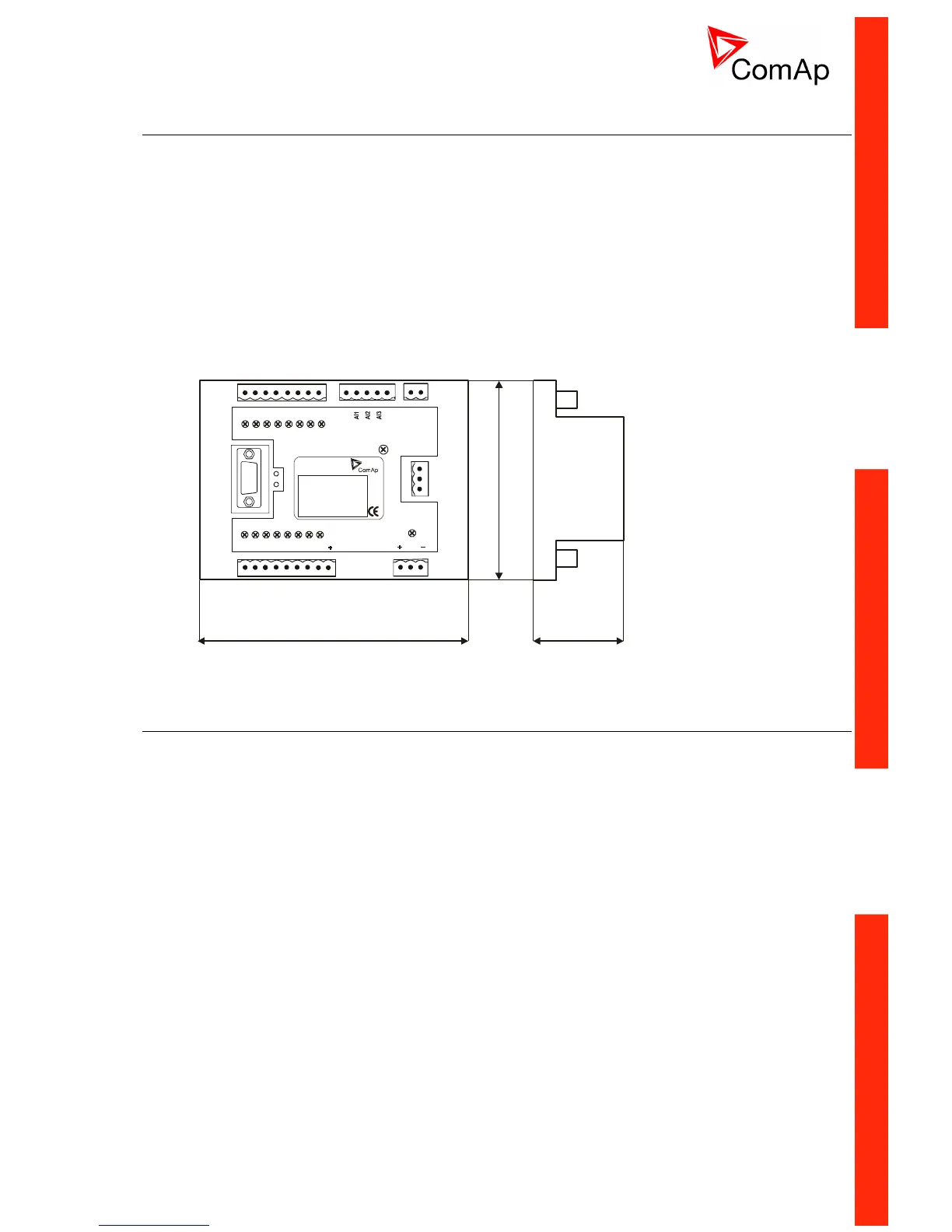
IGS-PTM
Extension module with 4 analog inputs, 8 Binary I/O. All I/O can be configured to any logical function or
protection - see chapter Binary inputs, Binary outputs and Analog inputs.
IGS-PTM module is connected on InteliDrive CAN1 bus. The corresponding module Address (1 to 4) must
be set on module and in controller configuration. Communication fail is indicated in controller Alarm list and
by binary output CommBIN fail, CommBOUT fail, CommAIN fail. Use DriveConfig PC tool for controller
configuration.
Any analog input can be configured for range:
0 – 250 (suitable for Pt100, Ni100),
0 – 100 mV (suitable for thermocouples),
0 – 20 mA.
Detail description see in IGS-PTM-1.0.pdf manual.
IGS-PTM unit is DIN rail (35mm) mounted.
I-AOUT8
Extension module with 8 analog outputs. All outputs can be configured to any logical function - see chapter
Analog outputs.
I-AOUT8 module is connected on InteliDrive CAN1 bus. The corresponding module Address 1 to 4 (default
1) must be set on module (by Adr.1 and Adr.2 jumpers) and in controller configuration. Communication fail is
indicated in controller Alarm list and by binary output Comm AOUT fail. Use DriveConfig PC tool for
controller configuration.
Each analog output can be switched by jumper for.
- 0 to 20 mA (default)
- 0 to 10 VDC
- Pwm (Pulse Width Modulation on 1,2 kHz)
Module is 35 mm DIN rail mounted. CAN1 terminating 120 resistor jumper is connected in default. AGND
terminals are on the same potential.

 Loading...


