ID-DCU-MARINE-2.2.2, ©ComAp – June 2015 - 49 -
ID-DCU-MARINE-2.2.2.pdf
Hardware connection
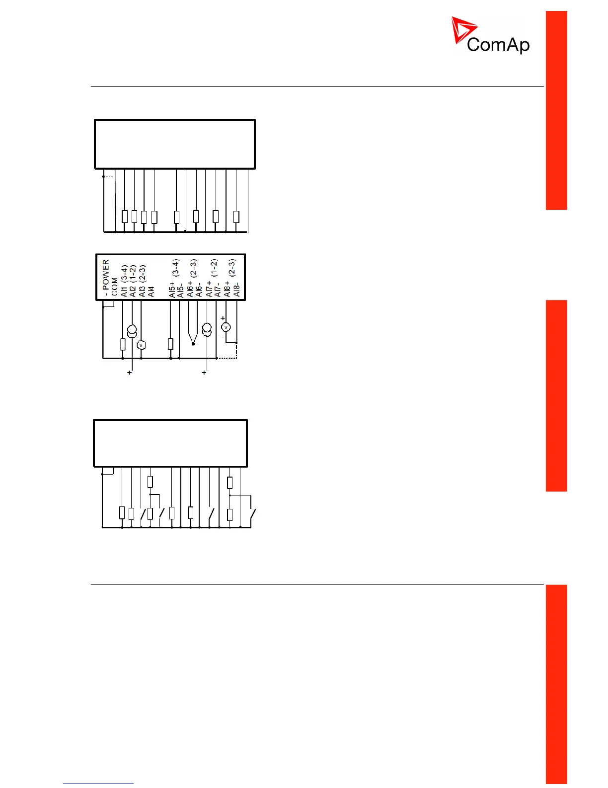
Connection of ID-DCU MARINE analog inputs
ID-CU
COM
- POWER
AI4
AI3
AI2
AI1
AI6-
AI6+
AI5-
AI5+
AI8-
AI8+
AI7-
AI7+
All jumpers in position (3-4)
Standard connection of resistive sensors to ID-DCU
MARINE analog inputs AI1 to AI8. The COM
terminal must be always connected to the negative
power terminal.
Different sensors connection to ID-DCU MARINE.
AI configuration jumpers must be in corresponding
position and corresponding DriveConfig
configuration according to used sensor.
Analog input common terminal COM has to be
connected to ID minus Power supply terminal.
Mixed connection of ID-DCU MARINE analog
inputs:
AI2, AI7 – current sensor
AI1, AI5 – resistive sensor
AI3, AI8 – voltage input
AI6 – thermocouple (voltage)
AI4 – Not used
ID-CU
COM
- POWER
AI4
AI3
AI2
AI1
AI6-
AI6+
AI5-
AI5+
AI8-
AI8+
AI7-
AI7+
All jumpers in position (3-4)
2x 470 ohms
2x 470 ohms
Mixed connection of InteliDrive analog inputs:
AI1, AI2, AI5, AI6 – resistive sensor
AI3, AI7 – binary input
AI4, AI8 – three state input
Analog input common terminal COM has to be
connected to ID minus Power supply terminal.
To ensure a proper function use shielded cables, especially for length over >3m.
Analog inputs on IS-AIN8
IS-AIN8 analog inputs can be configured to
Resistor two wire input
Resistor three wire input
Current input
Thermocouple input
Voltage input
Select sensor characteristic from the list or define user sensor characteristic in DriveConfig.

 Loading...


