ID-DCU-MARINE-2.2.2, ©ComAp – June 2015 - 50 -
ID-DCU-MARINE-2.2.2.pdf
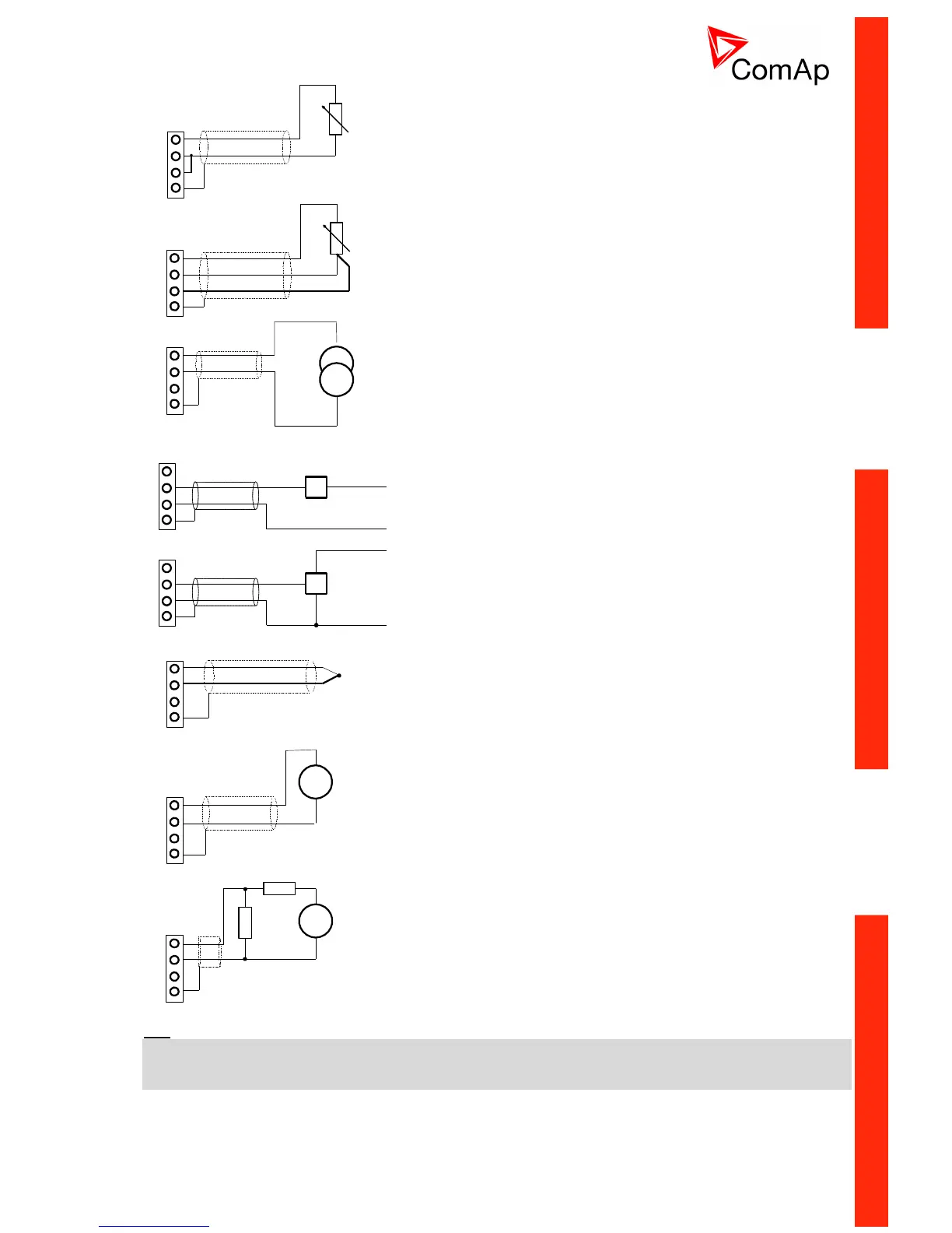
Resistor sensor input – two wire connection.
Range 0 to 2400 .
Pt100, Pt1000, Ni100, Ni1000
D terminal is shielding
Resistor sensor input – three wire connection.
Range 0 to 2400 .
Pt100, Pt1000, Ni100, Ni1000 – recommended.
D terminal is shielding
Passive current sensor (current source is in IS-AIN8)
Range 0 to + 20 mA or 4 to + 20 mA
D terminal is shielding
A
B
C
D
+
+24 VDC
0 VDC
Sensor
mA
A
B
C
D
+
+24 VDC
0 VDC
Sensor
mA
Active current sensor (current source is in sensor)
Range –20mA to +20 mA or 4 to + 20 mA
D terminal is shielding
Thermocouple J, K, L
D terminal is shielding
From IS-AIN8 hardware version 5.1 can be B thermocouple
terminal connected to frame.
Voltage input
Range 0 to + 2500 mV.
Voltage range is 0 to ± 1000 mV.
D terminal is shielding
For 10V input voltage range connect external resistors R1, R2
and select sensor characteristic 10V.
R1=10 kΩ, R2=2,7 kΩ
D terminal is shielding
Hint
Thermocouples connected to IS-AIN8 hardware versions below 5.0 must be galvanically separated from the
frame.
If the thermocouples are connected to IS-AIN8, appropriate jumpers must be removed (see rear sticker).

 Loading...


