ID-DCU-MARINE-2.2.2, ©ComAp – June 2015 - 55 -
ID-DCU-MARINE-2.2.2.pdf
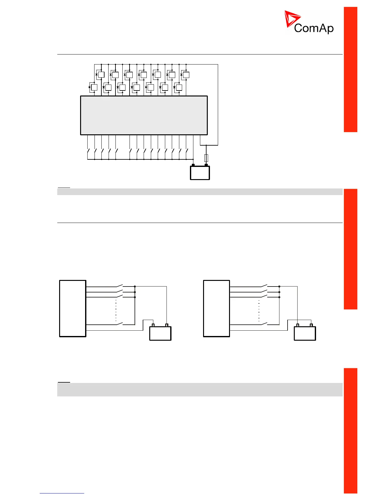
Binary inputs / outputs on ID-DCU MARINE
Use wiring cables min. of 1.0 mm
2
to ensure proper function.
+24VDC
0 VDC
BI 1
BI 2
BI 3
BI 4
BI 5
BI 6
BI 7
BI 8
BI 9
BI 10
BI 12
BI 13
BI 14
BI 11
+ -
BO 7
BO 8
BO 9
BO 10
BO 12
BO 13
BO 14
BO 11
ID-DCU
BO 1
BO 2
BO 3
BO 4
BO 5
BO 6
Hint:
Incorrect polarity of the binary output connection may cause a damage of the binary outputs.
Binary inputs on IS-BIN16/8
There are two groups of eight Binary inputs BI1 to BI8 and BI9 to BI16. Each group has a separate Common
terminal COM1 and COM2. The Common terminal can be connected to positive or negative pole – see
following drawing. Binary inputs are galvanically separated from IS-BIN16/8 power supply.
A Binary inputs Common terminal is connected to
positive supply terminal, Binary inputs contacts are
closed to negative supply terminals.
Binary inputs common terminal is connected to
negative supply terminal, Binary inputs contacts are
closed to positive supply terminals.
BI 1 (BI 9)
BI 2 (BI 10)
BI 3 (BI 11)
BI 8 (BI 16)
COM 1 (COM 2)
+
8 - 36 V
-
IS-BIN 16/8
+
8 - 36 V
-
BI 1 (BI 9)
BI 2 (BI 10)
BI 3 (BI 11)
BI 8 (BI 16)
COM 1 (COM 2)
IS-BIN 16/8
Input voltage range for opened contact is from 8 VDC to Power supply VDC. Input voltage range for closed
contact is from 0 to 2 VDC. Voltage level is defined between Binary input and Binary input COM terminal and
does not depend on “positive” or “negative” connection.
Hint:
It is recommended to separate inputs by diodes when two or more binary inputs are connected in parallel to
avoid wrong input activation when one controller is switched off.

 Loading...


