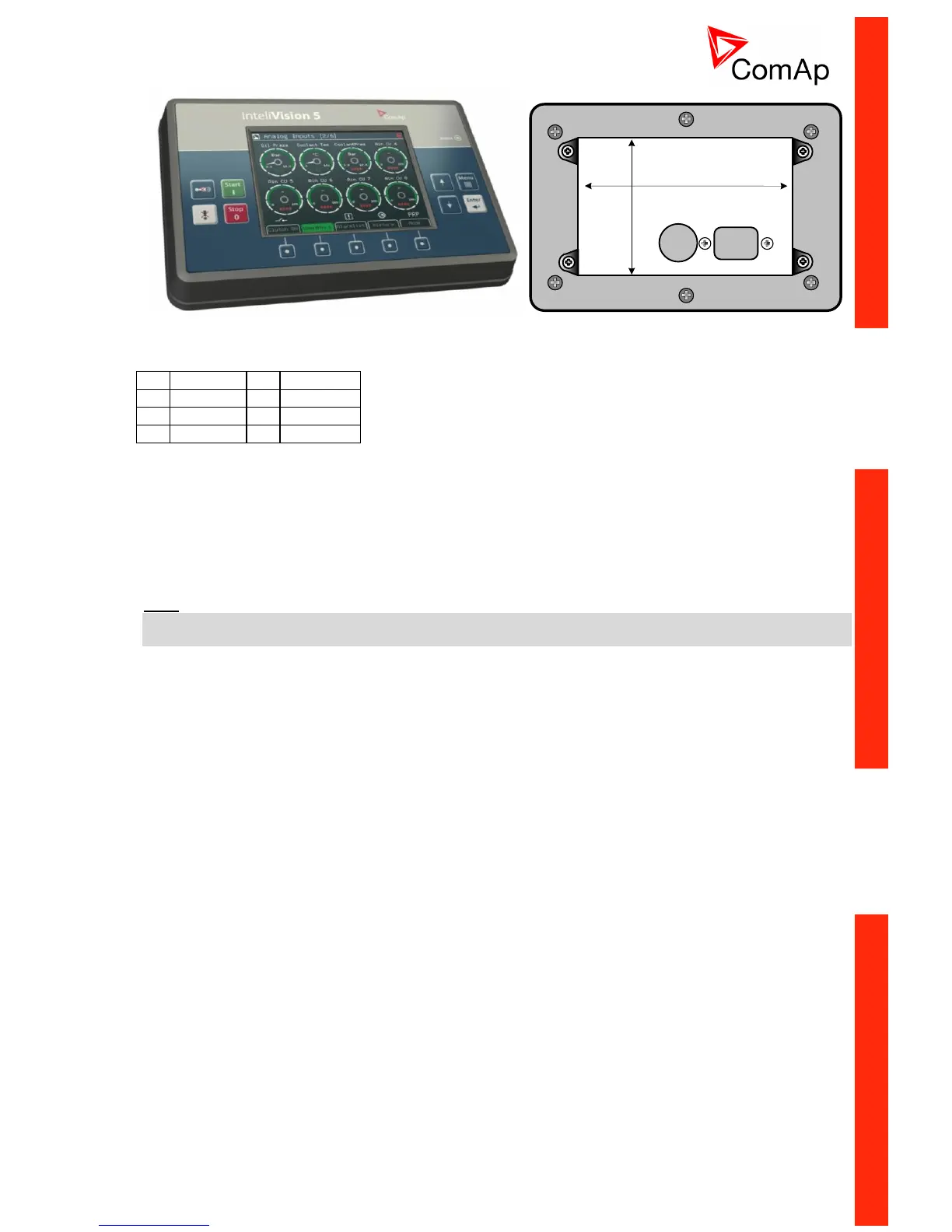
EasyManuals Logo

ComAp InteliDrive DCU Marine Reference Guide

ComAp InteliDrive DCU Marine
168 pages
To Next Page IconTo Next Page
To Previous Page IconTo Previous Page
Page #17 background imageLoading...
Page #17 background image
ID-DCU-MARINE-2.2.2, ©ComAp June 2015 - 17 -
ID-DCU-MARINE-2.2.2.pdf
170 (6.7")
110 (4.3")
InteliVision 5 CAN connector wiring
1
GND
5
UBatt
2
A/B IN
6
CAN-L
3
BO-A
7
COM
4
BO-B
8
CAN-H
1 - 5 Power supply 8 36VDC
6 - 8 CAN bus (with galvanic separation)
3 - 4 Binary output configured for Horn function. It is Solid State Relay with galvanic separation. Max
36VDC/0,5A (like free contact).
2 1 Analog/Binary Input for display and buttons backlit control. Connect resistive pot for continuous
backlit change: 0 ~ 0%; 2400 ~ 100%. Or just place contact to switch between 0% and 100%
intensity.
Note:
It is possible to connect up to five InteliVision 5 CAN or four InteliVision 8 displays to common CAN2 bus.
The display addresses must be different in this case.

Table of Contents

Other manuals for ComAp InteliDrive DCU Marine

Questions and Answers:

Question and Answer IconNeed help?

Do you have a question about the ComAp InteliDrive DCU Marine and is the answer not in the manual?

ComAp InteliDrive DCU Marine Specifications

General IconGeneral
BrandComAp
ModelInteliDrive DCU Marine
CategoryController
LanguageEnglish

Related product manuals